
Spacecraft information processing unit radiation degradation measuring device and method

A space vehicle and measuring device technology, applied in the direction of measuring devices, measuring electricity, measuring electrical variables, etc., can solve the problems that are not suitable for satellites, etc., and achieve the effect of less power consumption and less FPGA resources

Active Publication Date: 2017-02-22
HARBIN INST OF TECH
View PDF6 Cites 3 Cited by
  • Summary
  • Abstract
  • Description
  • Claims
  • Application Information

AI Technical Summary

Problems solved by technology

[0006] The purpose of the present invention is to solve the shortcoming that the test method of the prior art requires external measurement equipment and is not suitable for actual use on satellites, and proposes a radiation degradation measurement device and method for an information processing unit of a space vehicle

Method used


Image

  • Spacecraft information processing unit radiation degradation measuring device and method
  • Spacecraft information processing unit radiation degradation measuring device and method
  • Spacecraft information processing unit radiation degradation measuring device and method

Examples


specific Embodiment approach 1

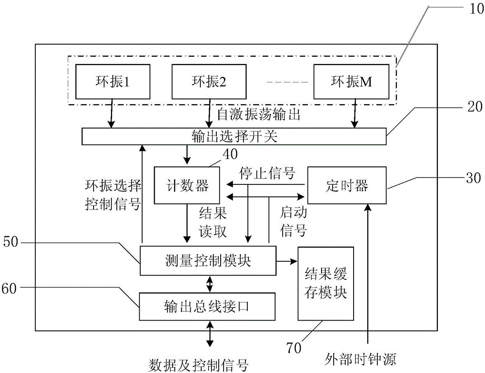
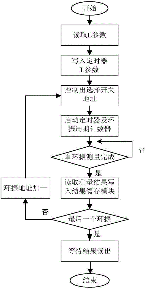
[0022] Specific implementation mode 1: The radiation degradation measurement device of the spacecraft information processing unit in this implementation mode is as follows: figure 1 As shown, the measurement device is arranged inside the FPGA device of the aircraft, including the ring vibration group 10, the output selection switch 20, the counter 40, the timer 30, the measurement control module 50 and the output bus interface 60, wherein the ring vibration group 10 Including at least one ring oscillator unit, the output selection switch 20 is used to select one from all ring oscillator units to provide a frequency signal for the counter 40 through address changes, and the frequency signal is used to reflect the degree of degradation of the FPGA device; The timer 30 is configured to have a predetermined timing duration, and when the timing duration is reached, a stop signal is sent to the counter 40 and the measurement control module 50; 40 and the timer 30 send a start signal...

specific Embodiment approach 2

[0034] Embodiment 2: The difference between this embodiment and Embodiment 1 is that the radiation degradation measurement device of the spacecraft information processing unit may further include a result buffer module 70 for buffering the frequency signals stored in the measurement control module.

[0035] The advantage of this setting is that it can realize the fast readout of the ring vibration test results, reduce the bus overhead, store the ring vibration test results in the on-chip memory uniformly, wait for all the tests to be completed, and read them out uniformly. If the data reading rate is not considered, the result cache module 70 can be canceled, and after each ring vibration test is completed and the result is sent, the next ring vibration test is performed.

[0036] Other steps and parameters are the same as those in Embodiment 1.

specific Embodiment approach 3

[0037] Embodiment 3: The difference between this embodiment and Embodiment 1 or 2 is that the ring oscillator unit includes an odd number of NOT gates, the NOT gates are connected end to end, and the input end of the first NOT gate is connected to the last NOT gate. After the output end of the output terminal is connected, it is connected with the output selection switch.

[0038] Other steps and parameters are the same as those in Embodiment 1 or Embodiment 2.


PUM


Abstract

The present invention relates to a spacecraft information processing unit radiation degradation measuring device and method. According to an existing test method, an externally connected measuring device is required, and as a result, the method is not suitable for the actual use condition of a satellite, while, with the spacecraft information processing unit radiation degradation measuring device and method of the invention adopted, the above condition can be avoided. The spacecraft information processing unit radiation degradation measuring device includes a ring vibration group, an output selection switch, a counter, a timer, a measurement control module and an output bus interface; the output selection switch is used for selecting one of ring vibration units, so that the selected ring vibration unit can provide frequency signals for the counter, wherein the frequency signals are used for reflecting the degradation degree of an FPGA device; after the timing duration of the timer is over, the timer sends stopping signals to the counter and the measurement control module; the measurement control module can send startup signals to the counter and the timer; and the output bus interface is used for reading the frequency signals in the measurement control module to a bus. The invention also includes a spacecraft information processing unit radiation degradation measurement method. The present invention is applicable to a spacecraft.

Description

technical field [0001] The invention relates to a space vehicle performance measurement method, in particular to a space vehicle information processing unit radiation degradation measurement device and method. Background technique [0002] In recent years, FPGA has been more and more widely used in the aerospace field at home and abroad. As early as in the Pathfinder launched by NASA in 1996, FPGA assumed important functions such as control, data management, and power management. The FEDSAT-1 satellite launched in Australia in December 2002 applied FPGA reconfigurable technology to aerospace vehicles for the first time. In 2003, SRAM-type FPGA was used in the Mars Rover, which completed the control of key ignition equipment and motor equipment, which attracted widespread attention in the aerospace field. As the performance of FPGA continues to improve, it has been widely used in the aerospace field. According to statistics, as of 2010, FPGA has been applied in more than 60...

Claims


Application Information

Patent Timeline
IPC IPC(8): G01R31/305G01R31/3181G01R31/319
CPCG01R31/305G01R31/3181G01R31/31915
Inventor 彭宇马宁王少军刘大同厉明坤彭喜元
Owner HARBIN INST OF TECH
Learn More