Array substrate and display device

An array substrate and substrate technology, which is applied in the direction of instruments, semiconductor devices, optics, etc., can solve the problems of uneven thickness of alignment layer, poor display, uneven diffusion of alignment liquid, etc., and achieve the effect of preventing uneven diffusion

Inactive Publication Date: 2017-02-22
BOE TECH GRP CO LTD +1
View PDF6 Cites 20 Cited by
  • Summary
  • Abstract
  • Description
  • Claims
  • Application Information

AI Technical Summary

Problems solved by technology

Before spraying the alignment liquid, since the via hole 21 is provided in the planarization layer 2, it is not difficult to see that the surface layer of the array substrate is not flat (the position of the dotted square box), and there are differences in the morphology, so the alignment liquid After spraying on the surface, the diffusion speed of the alignment liquid at the position corresponding to the via hole 21 is obviously different from the diffusion speed at other positions, so the problem of uneven diffusion of the alignment liquid is likely to occur, resulting in the thickness of the formed alignment layer Inhomogeneity, applying the array substrate to a display device will lead to poor display

Method used


Image

  • Array substrate and display device
  • Array substrate and display device
  • Array substrate and display device

Examples


Embodiment 1

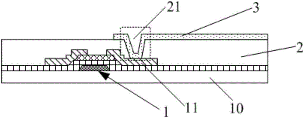
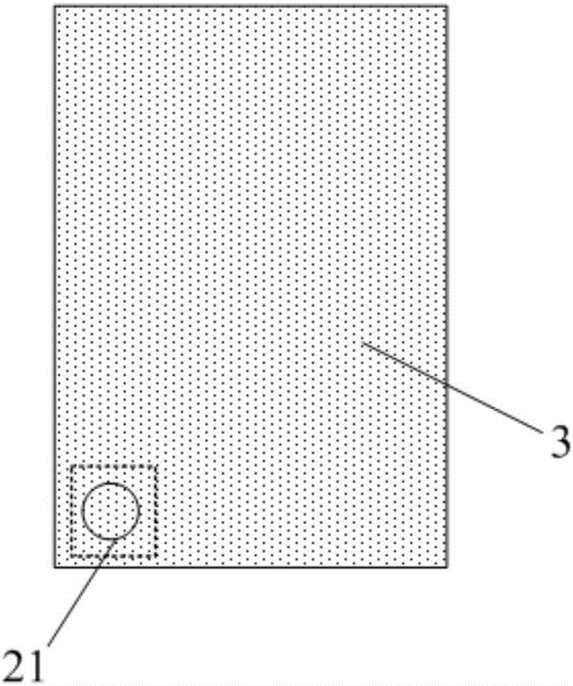
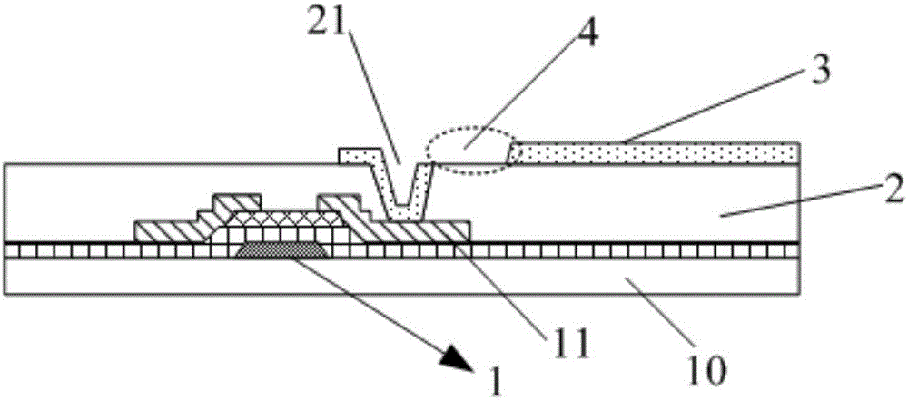
[0040] This embodiment provides an array substrate, which includes a substrate, a via hole located above the substrate, and a diffusion part; wherein, the orthographic projection of the diffusion part on the substrate is connected to the orthographic projection of the via hole on the substrate; the diffusion part is used to The alignment liquid at the position of the via hole is diffused.

[0041] The array substrate in this embodiment is provided with a diffusion part for diffusing the alignment liquid at the position of the via hole, and the orthographic projection of the diffusion part on the substrate is in contact with the orthographic projection of the via hole on the substrate. It can be seen that the concave surface corresponding to the position of the via hole on the surface of the array substrate on which the alignment liquid is not formed is excessively connected to other positions through the surface of the corresponding position of the diffusion part, and then when...

Embodiment 2

[0066] This embodiment provides a display device, which includes the array substrate in Embodiment 1. Therefore, the display device has a better display effect.

[0067] Wherein, the display device can be a liquid crystal display device or an electroluminescent display device, such as any product or component with a display function such as a liquid crystal panel, an electronic paper, a mobile phone, a tablet computer, a television, a monitor, a notebook computer, a digital photo frame, a navigator, etc. .


PUM

PropertyMeasurementUnit
lengthaaaaaaaaaa
widthaaaaaaaaaa
widthaaaaaaaaaa

Abstract

The invention provides an array substrate and a display device and belongs to the technical field of display. The array substrate comprises a substrate body, a via hole and a diffusion portion, wherein the via hole and the diffusion portion are positioned above the substrate body, orthographic projection of the diffusion portion on the substrate body is connected with that of the via hole on the substrate body, and the diffusion portion is used for diffusing orientation liquid at the position of the via hole. The array substrate has the advantages that the diffusion portion capable of diffusing the orientation liquid at the position of the via hole is arranged, the orthographic projection of the diffusion portion on the substrate body is connected with that of the via hole on the substrate body, and accordingly the orientation liquid at the corresponding position of the via hole is guided from the corresponding position of the diffusion portion when the surface of the array substrate is sprayed with the orientation liquid to enable the orientation liquid at the corresponding position of the via hole to diffuse evenly, and the problem of poor display due to uneven diffusion of the orientation liquid can be prevented.

Description

technical field [0001] The invention belongs to the field of display technology, and in particular relates to an array substrate and a display device. Background technique [0002] A Liquid Crystal Display (LCD for short) is one of the commonly used display devices at present. Generally, a liquid crystal display includes: an array substrate and a color filter substrate oppositely arranged, and a liquid crystal layer arranged between the array substrate and the color filter substrate. [0003] Such as figure 1 and 2 As shown, the array substrate generally includes a substrate 10; a thin film transistor 1 formed on the substrate 10; a planarization layer 2 formed on the layer where the thin film transistor 1 is located, and the planarization layer 2 corresponds to the drain 11 of the thin film transistor 1 A via hole 21 is provided at the position; a pixel electrode 3 is formed above the planarization layer, and the pixel electrode is connected to the drain electrode 11 of ...

Claims


Application Information

Patent Timeline
Patent Type & Authority Applications(China)
IPC IPC(8): G02F1/1362G02F1/1368G02F1/1337
CPCG02F1/1337G02F1/136227G02F1/1368G02F1/136295H01L27/1248H01L27/1214H01L33/38G02F1/133711G02F1/1343G02F1/133776G02F1/1362G02F1/133357G02F1/136286G02F2201/121G02F2201/123H01L27/124
Inventor 刘利萍张南红汤展峰
Owner BOE TECH GRP CO LTD
Why Eureka
Try Eureka