
Method and system for measuring clock synchronization based on double buffer areas
A technology of clock synchronization and measurement method, applied in general control system, control/adjustment system, radio-controlled timer, etc., can solve the problems of frequent time synchronization, insufficient measurement accuracy, low efficiency, etc., and achieve easy execution and data transmission Fast and stable, the effect of improving equipment operation efficiency
- Summary
- Abstract
- Description
- Claims
- Application Information
AI Technical Summary
Problems solved by technology
Method used
Image

Examples
Embodiment Construction
[0038] In order to better illustrate the present invention, the present invention will be described in detail with a preferred embodiment and with accompanying drawings, specifically as follows:
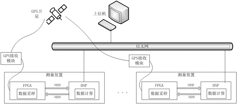
[0039] Such as figure 1 As shown, the present embodiment provides a kind of clock synchronous measuring system based on double buffer zone, comprises DSP system and FPGA system, and FPGA system comprises several FPGAs that are arranged in different measurement devices, and DSP system comprises several FPGAs that are arranged in different measuring devices. DSP within the measuring device. Among them, FPGA is used for data sampling to obtain sampled data; DSP is used for receiving sampled data from FPGA and performing data calculation.
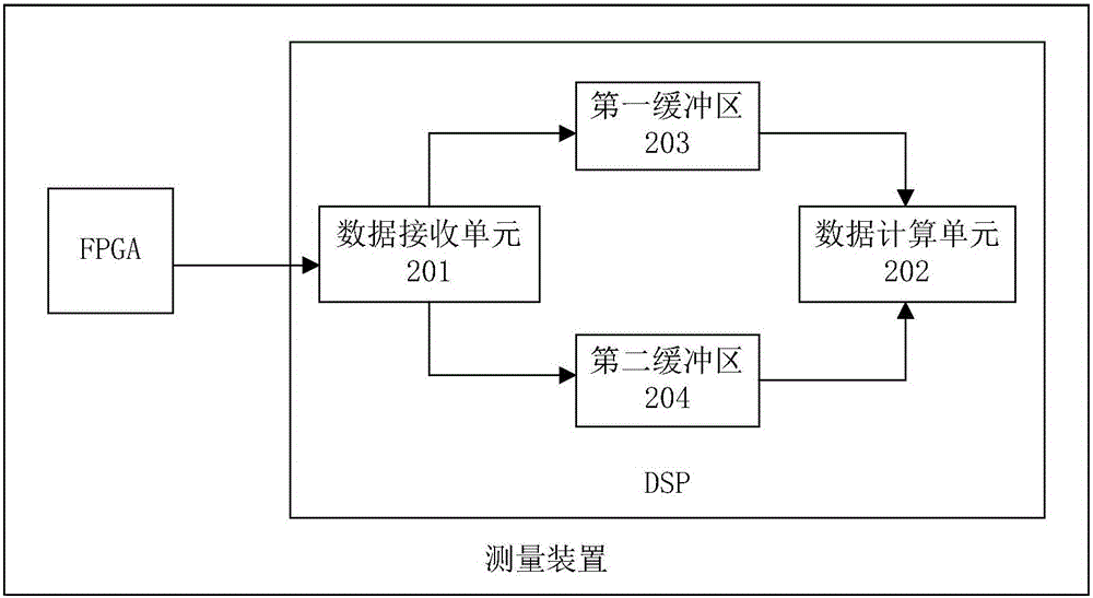
[0040] Such as figure 2 As shown, each DSP in this embodiment includes: a data receiving unit 201 , a data calculating unit 202 , a first buffer 203 and a second buffer 204 .
[0041] The data receiving unit 201 is used for receiving the sampling ...
PUM
 Abstract
Description
Claims
Application Information