Method for optimizing contaminated soil restoration scope and boundary

A technology of polluted soil and optimization method, which is applied in the restoration of polluted soil, special data processing applications, instruments, etc., can solve problems such as cumbersome algorithms and multiple measurement inflection points, achieve strong operability, reduce computing workload, and operate easy effect

Active Publication Date: 2017-02-22
BCEG ENVIRONMENTAL REMEDIATION CO LTD
View PDF5 Cites 19 Cited by
  • Summary
  • Abstract
  • Description
  • Claims
  • Application Information

AI Technical Summary

Problems solved by technology

[0009] The purpose of the present invention is to solve the problems in the above-mentioned prior art, that is, the algorithm of the prior art is relatively cumbersome...

Method used


Image

  • Method for optimizing contaminated soil restoration scope and boundary
  • Method for optimizing contaminated soil restoration scope and boundary
  • Method for optimizing contaminated soil restoration scope and boundary

Examples


Embodiment 1

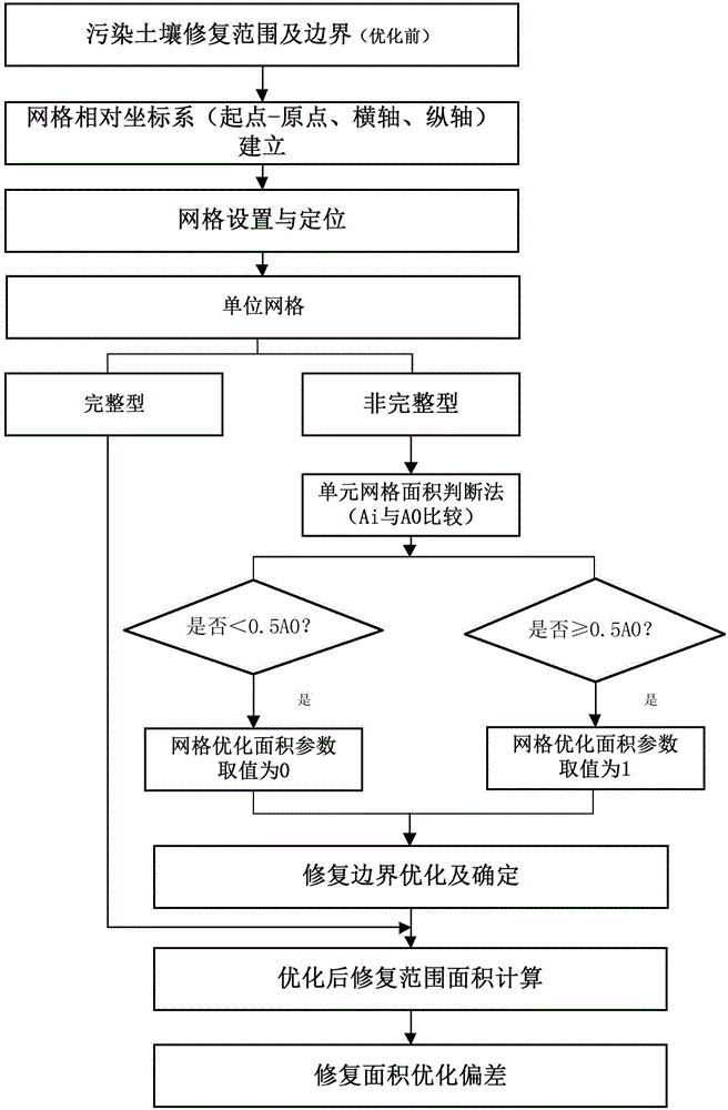
[0049] This example is a polluted site of a dye factory in Wuhan. The repaired area determined (before optimization) by the site investigation and risk assessment of this plot (A plot) is 10798m2 2 , the target pollutants are mainly organic pollutants such as chlorobenzene and benzene series. Taking plot A of this site as an example, the optimization method for the boundary and scope of soil pollution remediation, such as figure 1 As shown, the specific steps are as follows:

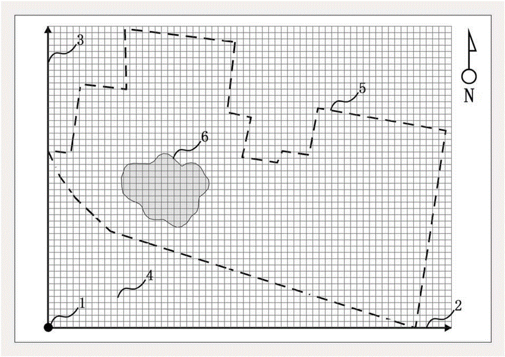
[0050] Step 1: Establish a relative coordinate system. The coordinate origin (grid starting point) 1 is located at the southwesternmost end of the polluted site. The corner point of an existing building is selected as the grid reference point, and the point is accurately positioned and recorded by GPS. Set the horizontal axis X2 to be east-west, and the vertical axis Y3 to be north-south. The pollution boundary and scope 6 (before optimization) of the polluted plot (Plot A) and the building red line 5 ...

Embodiment 2

[0075] This example is a contaminated site in a heavy steel area in Chongqing, and the main target pollutants in the soil are As, Cd, Cr, Cu, Hg, Ni, Pb, Sb, Zn and other heavy metals. Briefly describe the soil remediation scope and boundary optimization process of the local plots.

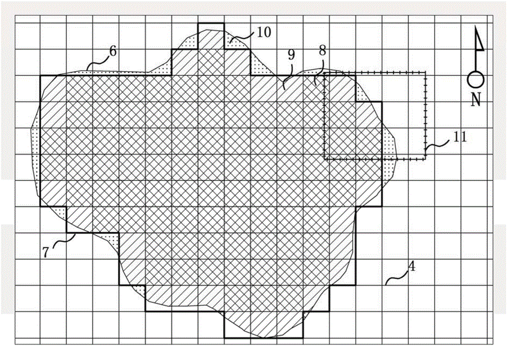
[0076] like Figure 4 , Figure 5As shown, are respectively two representative plots in the polluted site of this embodiment, the remediation scope and boundaries of the B plot and the C plot, and the schematic diagram of the "dichotomy" optimization.

[0077] Plots B and C adopt the same relative coordinate system and a unit grid of 10m×10m. The coordinate system establishment and grid division methods are the same as those in Embodiment 1, and will not be repeated here.

[0078] This embodiment only uses the method of the present invention to optimize the calculation parameters and result list of the representative polluted plots B and C. The calculation parameters and results of the optimized...


PUM


Abstract

The invention relates to a method for optimizing contaminated soil restoration scope and boundary. According to the method, a relative coordinate system is established, a unit grid is located and subjected to grid processing, a dichotomy method is used to abandon or improve the optimization of the unit grid, a contaminated land area drawn according to a geostatistical analysis interpolation method is located in the unit grid, the optimized restoration boundary comprises multiple linear polylines, the measurement inflection point is greatly reduced, and meanwhile, the relative error of the restoration areas before and after optimization is controlled to be within a range from plus or minus 1% to plus or minus 5%. The method aims at the problems of artificial increase of the implementation difficulty of the restoration work and the relatively large measurement work amount caused by the universal low regularity, the curve boundary and the existence of a large quantity of inflection points in the restoration scope and boundary determined in a current ground investigation stage, the provided optimization method is relatively high in operability, and the optimum-determined restoration boundary can be conveniently restored after rapid measurement. The method is suitable for optimum determination of the soil restoration scope and boundary in the optimization design stage of contaminated site investigation and soil restoration work.

Description

technical field [0001] The invention belongs to the technical field of polluted soil investigation, monitoring and restoration engineering, and in particular relates to an optimization method for the scope and boundary of contaminated soil restoration. Background technique [0002] In recent years, with the promulgation of my country's "Soil Pollution Prevention and Control Action Plan" (referred to as "Soil Ten Measures"), the treatment of contaminated sites has risen to the national level. At the same time, the Ministry of Environmental Protection promulgated a series of related technical guidelines on pollution investigation, risk assessment, monitoring and remediation of polluted sites. The investigation, risk assessment, monitoring, and engineering restoration of soil pollution control are gradually standardized. [0003] The premise of soil remediation projects is to obtain more accurate and reliable boundaries and scope of soil pollution, so the pollution investigati...

Claims


Application Information

Patent Timeline
IPC IPC(8): G06F17/50G06Q10/04B09C1/00
CPCB09C1/00G06F30/00G06Q10/04
Inventor 李书鹏杨乐巍王艳伟张岳郝弟韩春媚
Owner BCEG ENVIRONMENTAL REMEDIATION CO LTD
Why Eureka
Try Eureka