
An optimization method for the scope and boundary of contaminated soil remediation
A technology of polluted soil and optimization method, which is applied in the restoration of polluted soil, data processing applications, instruments, etc., can solve the problems of cumbersome algorithms, multiple measurement inflection points, etc., achieve strong operability, reduce calculation workload, and easy operation Effect
- Summary
- Abstract
- Description
- Claims
- Application Information
AI Technical Summary
Problems solved by technology
Method used
Image

Examples
Embodiment 1
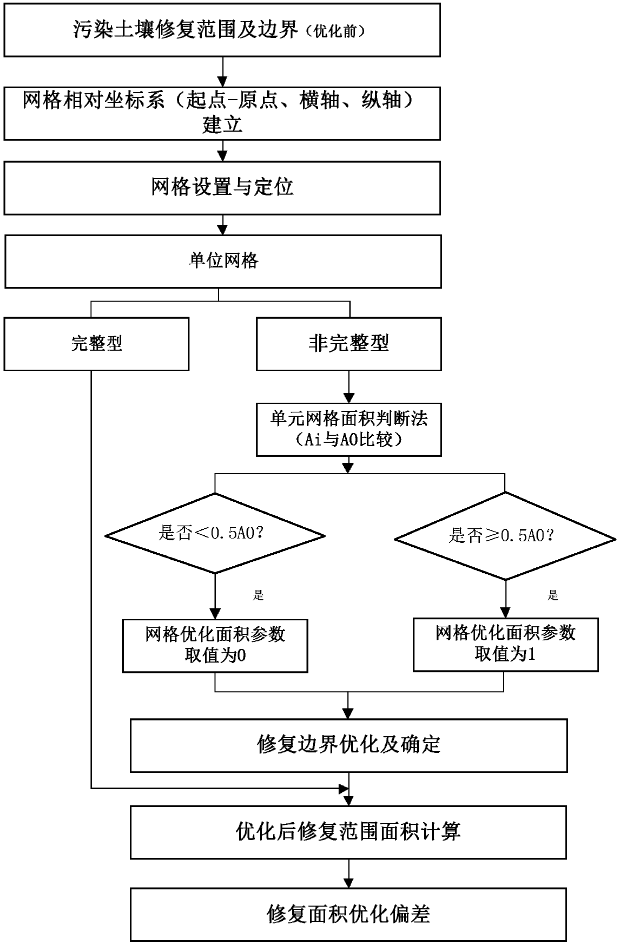
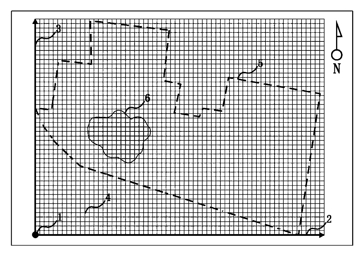
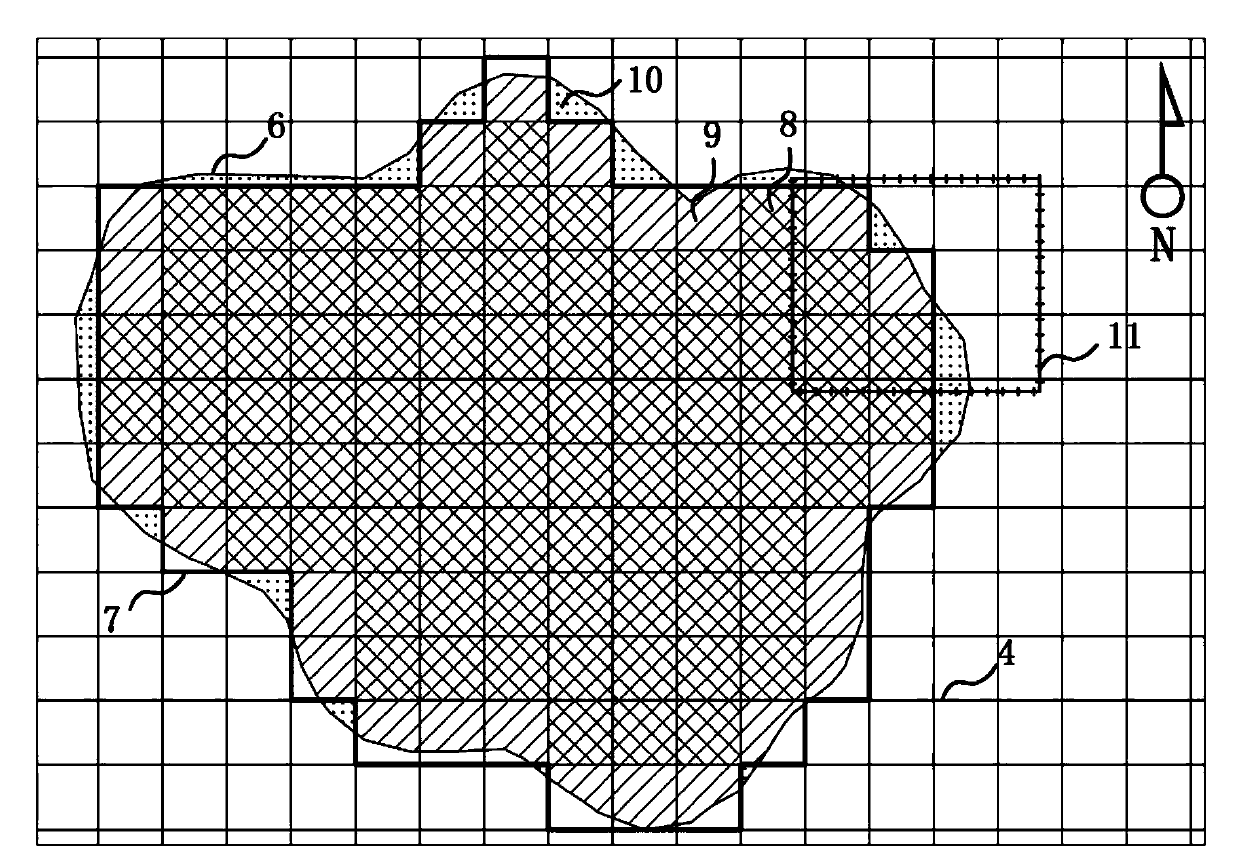
[0049] This example is a polluted site of a dye factory in Wuhan. The repaired area determined (before optimization) by the site investigation and risk assessment of this plot (A plot) is 10798m2 2 , the target pollutants are mainly organic pollutants such as chlorobenzene and benzene series. Taking plot A of this site as an example, the optimization method for the boundary and scope of soil pollution remediation, such as figure 1 As shown, the specific steps are as follows:
[0050] Step 1: Establish a relative coordinate system. The coordinate origin (grid starting point) 1 is located at the southwesternmost end of the polluted site. The corner point of an existing building is selected as the grid reference point, and the point is accurately positioned and recorded by GPS. Set the horizontal axis X2 to be east-west, and the vertical axis Y3 to be north-south. The pollution boundary and scope 6 (before optimization) of the polluted plot (Plot A) and the building red line 5 ...
Embodiment 2
[0074] This example is a contaminated site in a heavy steel area in Chongqing, and the main target pollutants in the soil are As, Cd, Cr, Cu, Hg, Ni, Pb, Sb, Zn and other heavy metals. Briefly describe the soil remediation scope and boundary optimization process of the local plots.
[0075] like Figure 4 , Figure 5As shown, are respectively two representative plots in the polluted site of this embodiment, the remediation scope and boundaries of the B plot and the C plot, and the schematic diagram of the "dichotomy" optimization.
[0076] Plots B and C adopt the same relative coordinate system and a unit grid of 10m×10m. The coordinate system establishment and grid division methods are the same as those in Embodiment 1, and will not be repeated here.
[0077] This embodiment only uses the method of the present invention to optimize the calculation parameters and result list of the representative polluted land plots B and C. Among them, the calculation of the relative error ...
PUM
 Abstract
Description
Claims
Application Information