Cloud workflow scheduling method supporting any flow structure

A technology of process structure and scheduling method, which is applied in the fields of information technology and computer, and can solve the problems of inapplicability of algorithms, inability to describe workflow models, and inapplicability to cloud workflow environment.

Inactive Publication Date: 2017-02-22
BEIJING INSTITUTE OF TECHNOLOGYGY
View PDF0 Cites 24 Cited by
  • Summary
  • Abstract
  • Description
  • Claims
  • Application Information

AI Technical Summary

Problems solved by technology

[0003] Since the scheduling problem of cloud computing is an NP-hard (non-deterministic polynomial-hard) problem, this kind of problem can only seek an effective approximation algorithm and cannot be solved accurately. The current cloud workflow scheduling algorithm is mainly divided into best-effort based (best-effort based) workflow scheduling algorithm and workflow scheduling algorithm based on QoS constraint (QoSconstraint based) two categories, the former category of common algorithms are dynamic critical path algorithm DCP (Dynamic Critical Path) method, min- min method, HEFT (Heterogeneous Earliest FinishTime) method, etc. This type of scheduling algorithm only takes the minimum execution time as the scheduling goal, and is not suitable for commercial cloud workflow environments; the latter type of algorithm not only considers the workflow Execution time optimization, while considering the optimization of execution costs and non-functional indicators such as safety and reliability
Although there are many existing scheduling algorithms, most of them have certain limitations in practical application and do not have universal applicability to all workflow model structures, such as the work based on DAG (Directed Acyclic Gragh) graph Although the flow scheduling algorithm is simple and intuitive in expression, and has shown good performance in some practical applications, such an algorithm is not suitable for workflow scheduling problems with selection and loop logic control structures. The reason is It is a DAG diagram that cannot describe a workflow model with two logical structures of selection and circulation

Method used


Image

  • Cloud workflow scheduling method supporting any flow structure
  • Cloud workflow scheduling method supporting any flow structure
  • Cloud workflow scheduling method supporting any flow structure

Examples


Embodiment Construction

[0110] The content of the present invention will be further described below with reference to the accompanying drawings and specific embodiments.

[0111] The service provider received a task request submitted by the user at 8:00 am on June 16, 2016, and the user requested to get the task execution result at 10:05 am on June 16, 2016. Assume that it takes 2 hours and 2 minutes for the service provider to negotiate with the user, sign an agreement, and model workflow tasks and cloud service resources.

[0112] It can be seen that the deadline D proposed by the user is 10:05:00 this morning, and the earliest execution time of the workflow is 10:02:00, so the running period of the workflow must be less than 180s.

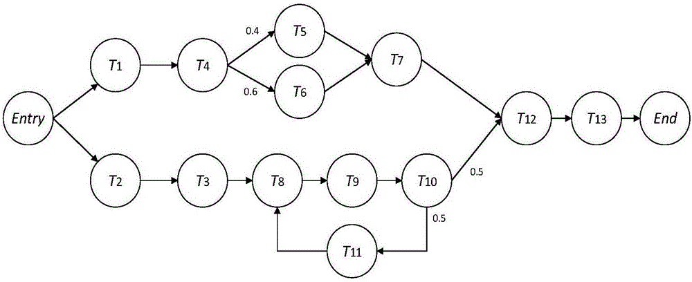
[0113] Step 1. Use a directed graph to model the workflow of tasks.

[0114] A task corresponds to a workflow, and a workflow is described by a triple Ω(T,Λ,D), where T is a node set, T=(T 1 , T 2 ...T 13 ), a directed graph such as figure 1 As shown, Λ is the dir...


PUM


Abstract

The invention mainly relates to a cloud workflow scheduling method supporting any flow structure, belongs to the field of information technologies and computers, and particularly relates to a cloud workflow scheduling algorithm which has universal applicability for various workflow models in a cloud computing environment and considers service quality indexes. According to the method, a task is modeled through a directed graph by taking a minimized cloud workflow execution expense as a scheduling target under a deadline constraint, so that simple and visual modeling advantages of a DAG graph are reserved and the method is suitable for workflow scheduling problems including logic structure selection and circulation; and static matching and dynamic adjustment of resources are subjected to task scheduling, so that the resource selection is optimized and very high universality is achieved.

Description

technical field [0001] The present invention mainly relates to a cloud workflow scheduling method that supports arbitrary process structures, and belongs to the field of information technology and computers. A Cloud Workflow Scheduling Algorithm for Quality of Service Indicators. Background technique [0002] With the development and maturity of computer Internet technology, cloud computing technology came into being. After nearly ten years of practice and exploration of cloud computing technology by major IT companies and related research institutions, cloud services have been accepted by more and more countries, enterprises, Personal favor and increasing demand have prompted many IT companies at home and abroad to launch their own cloud products. However, with the rapid development of cloud computing technology, the security, reliability and practicability of its products have attracted great attention from the supply and demand sides and scholars in related fields. Among...

Claims


Application Information

Patent Timeline
Patent Type & Authority Applications(China)
IPC IPC(8): G06Q10/06G06Q10/10
CPCG06Q10/0633G06Q10/103
Inventor 李慧芳杨睿韬张百海
Owner BEIJING INSTITUTE OF TECHNOLOGYGY
Why Eureka
Try Eureka