Groove-type barrier schottky structure for optimizing electric field on surface and manufacturing method of groove-type barrier schottky structure

A technology of surface electric field and manufacturing method, which is applied in the manufacturing of circuits, electrical components, semiconductor/solid-state devices, etc., can solve the problems of high temperature leakage, reliability failure, weak anti-surge ability, etc.

Inactive Publication Date: 2017-02-22
YANGZHOU YANGJIE ELECTRONIC TECH CO LTD
View PDF5 Cites 3 Cited by
  • Summary
  • Abstract
  • Description
  • Claims
  • Application Information

AI Technical Summary

Problems solved by technology

[0014] In view of the problems mentioned above and / or existing in the existing semiconductor packaging, the concentration of electric field lines on the top surface of the trench is prone to high temperature leakage, weak anti-surge capability, and easy to cause reliability failure, etc., the present invention is proposed

Method used


Image

  • Groove-type barrier schottky structure for optimizing electric field on surface and manufacturing method of groove-type barrier schottky structure
  • Groove-type barrier schottky structure for optimizing electric field on surface and manufacturing method of groove-type barrier schottky structure
  • Groove-type barrier schottky structure for optimizing electric field on surface and manufacturing method of groove-type barrier schottky structure

Examples


Embodiment Construction

[0055] In order to make the above objects, features and advantages of the present invention more comprehensible, the specific implementation manners of the present invention will be further described below in conjunction with specific drawings.

[0056] In the following description, a lot of specific details are set forth in order to fully understand the present invention, but the present invention can also be implemented in other ways that are different from those described here, and those skilled in the art can do so without departing from the connotation of the present invention. By analogy, the present invention is not limited by the specific examples disclosed below.

[0057] Secondly, the present invention is described in detail in combination with schematic diagrams. When describing the embodiments of the present invention in detail, for the convenience of explanation, the cross-sectional view showing the device structure will not be partially enlarged according to the g...


PUM

PropertyMeasurementUnit
lengthaaaaaaaaaa
thicknessaaaaaaaaaa
depthaaaaaaaaaa

Abstract

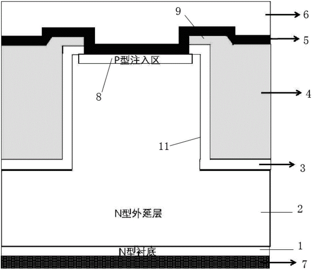
The invention relates to a groove-type barrier schottky structure for optimizing an electric field on the surface and a manufacturing method of the groove-type barrier schottky structure. The groove-type barrier schottky structure comprises a cellular groove, an active region and a terminal pressure ring which are located on a semiconductor substrate, wherein the groove-type barrier schottky structure is characterized in that the section of the groove-type barrier schottky structure is provided with an N-type substrate, an N-type epitaxial layer, a barrier metal located on the upper surface of the N-type epitaxial layer, a front metal and a back metal; the cellular groove comprises a groove in the upper part of the N-type epitaxial layer, an oxide layer grows on the inner wall and the top surface of the groove, conductive polycrystalline silicon is deposited into an inner cavity of the groove and a polycrystalline silicon shielding layer is arranged on the oxide layer on the top surface of the groove; and a P-type injection region is formed at the lower part of the barrier metal in the active region and is located at the upper part of the N-type epitaxial layer. According to the groove-type barrier schottky structure, a peak electric field on the surface can be optimized; the compression ability of the barrier metal on the surface is improved; electric leakage of a device is reduced; and the surge capacity and the high-temperature reliability are improved.

Description

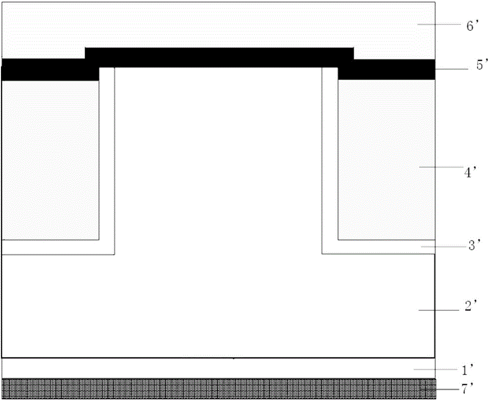
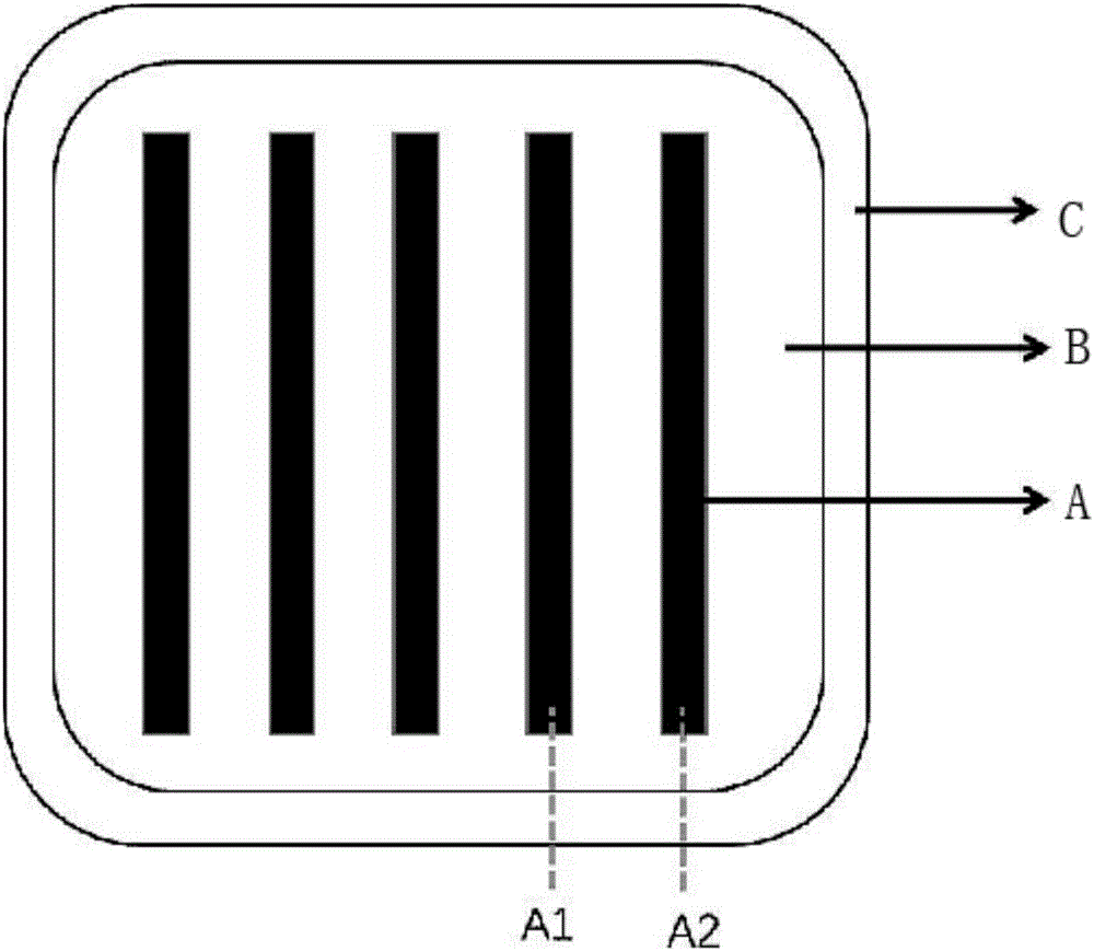
technical field [0001] The invention relates to a trench-type potential barrier Schottky structure with optimized surface electric field and a manufacturing method thereof, belonging to the technical field of semiconductors. Background technique [0002] The current traditional trench barrier Schottky structure such as figure 1 As shown, it includes N-type substrate 1', N-type epitaxial layer 2', thermal oxide layer 3', conductive polysilicon 4', barrier metal layer 5', front metal 6' and back metal 7'. [0003] The manufacturing method of the traditional trench barrier Schottky comprises the following steps: [0004] (1) Forming a trench etch barrier layer on the surface of the N-type epitaxial layer 2': [0005] (2) Perform trench etching; [0006] (3) Remove all trench etch barrier layers by wet etching; [0007] (4) A certain thickness of thermal oxide layer 3' is grown on the inner wall of the trench; [0008] (5) Deposit conductive polysilicon (LPPOLY) 4' in the t...

Claims


Application Information

Patent Timeline
Patent Type & Authority Applications(China)
IPC IPC(8): H01L29/872H01L29/47H01L21/329
CPCH01L29/47H01L29/66143H01L29/8725
Inventor 周祥瑞冷德武王毅
Owner YANGZHOU YANGJIE ELECTRONIC TECH CO LTD
Why Eureka
Try Eureka