
Driving protection circuit applied to fully-controlled electric power electronic device

A technology for power electronic devices and protection circuits, applied in the field of drive protection circuits, can solve problems such as limiting the application range of drive circuits, and achieve the effects of small size, configurable parameters, and small signal transmission delay

Pending Publication Date: 2017-02-22
716TH RES INST OF CHINA SHIPBUILDING INDAL CORP +1
View PDF0 Cites 1 Cited by
  • Summary
  • Abstract
  • Description
  • Claims
  • Application Information

AI Technical Summary

Problems solved by technology

However, the drive circuits currently on the market either focus on the detection of overcurrent conditions, or fail to achieve safe and reliable shutdown of high-power fully-controlled power electronic devices, thus limiting the application range of this type of drive circuit

Method used


Image

  • Driving protection circuit applied to fully-controlled electric power electronic device
  • Driving protection circuit applied to fully-controlled electric power electronic device
  • Driving protection circuit applied to fully-controlled electric power electronic device

Examples


Embodiment Construction

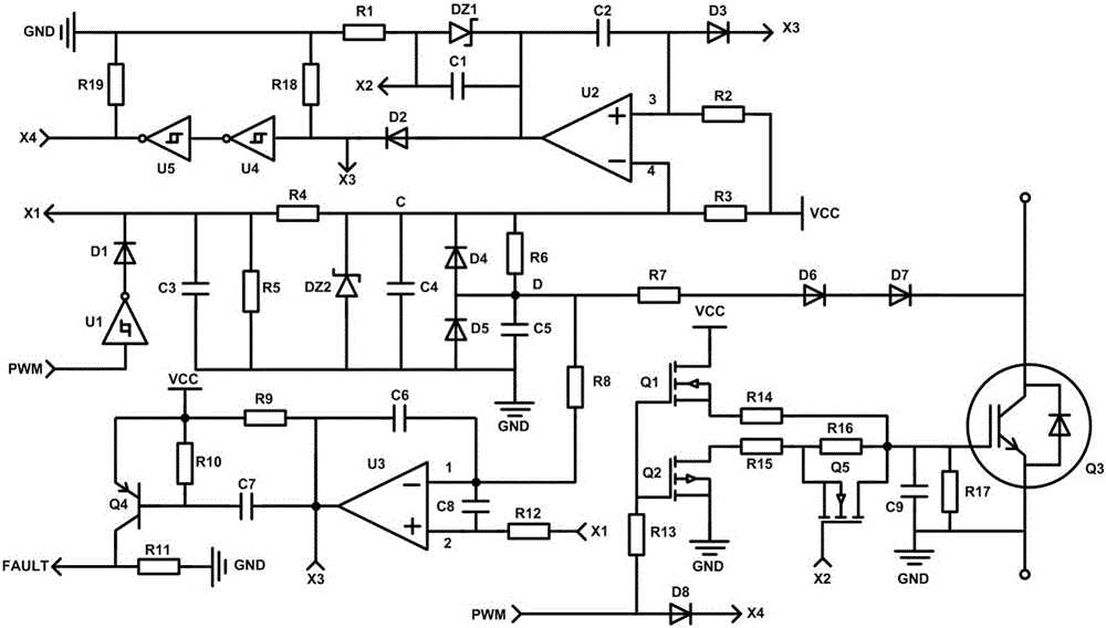
[0009] combine figure 1 , a drive protection circuit applied to fully controlled power electronic devices, including, power supply VCC, gate drive circuit, gate resistance shift circuit, V ce Voltage detection protection circuit, short circuit signal FAULT output circuit;

[0010] The power supply VCC is used to provide working voltage;

[0011] The input terminal of the gate drive circuit is connected with PWM pulses, which are used to provide output power and PWM pulses to the power electronic device Q3;

[0012] The gate resistor shift circuit is used for

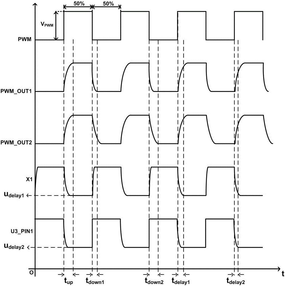
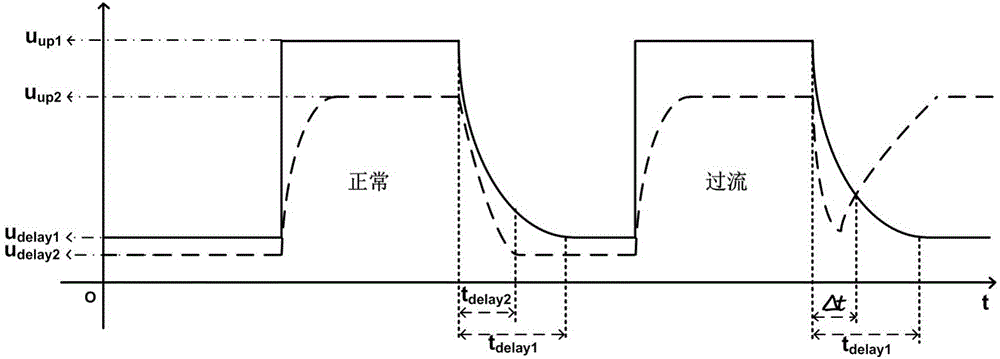
[0013] When the power electronic device Q3 is in the working state, the power electronic device Q3 has a small off time,

[0014] When the power electronic device Q3 is in an overcurrent state, the power electronic device Q3 has a relatively large turn-off time;

[0015] V ce The voltage detection protection circuit is used to detect whether an overcurrent occurs when the power electronic device Q3 is turned on;

...


PUM


Abstract

The invention provides a driving protection circuit applied to a fully-controlled electric power electronic device. The protection circuit comprises a power supply VCC, a grid driving circuit, a grid resistor gearshift circuit, a Vce voltage detection protection circuit and a short circuit signal FAULT output circuit, wherein the power supply VCC is used for providing a work voltage, an input end of the grid driving circuit is connected with PWM pulses, the grid driving circuit is used for providing an output power and the PWM pulses for the electric power electronic device, the grid resistor gearshift circuit is used for making the electric power electronic device have relatively short turn-off time when the electric power electronic device is in a work state or making the electric power electronic device have the relatively long turn-off time when the electric power electronic device is in an overcurrent state, the Vce voltage detection protection circuit is used for detecting whether the electric power electronic device generates overcurrent during device conduction, and the short circuit signal FAULT output circuit is used for outputting a FAULT signal to a control end when the electric power electronic device generates overcurrent during device conduction.

Description

technical field [0001] The invention relates to an electronic circuit technology, in particular to a drive protection circuit applied to full-control electric electronic devices. Background technique [0002] Fully-controlled power electronic devices (IGBT, MOSFET, etc.) are widely used in today's industrial fields, such as energy conversion modules in high-speed rail and EMUs, power inverter modules in solar and wind power generation, and inverters in various industrial servo drives. Transformation modules, etc., the core power devices that realize power conversion are fully-controlled power electronic devices (IGBT, MOSFET, etc.). High-power full-control power electronic devices (IGBT, MOSFET, etc.) are different from ordinary transistors, thyristors, etc., and these devices need to be equipped with dedicated drive protection circuits. A very important link in the drive protection of high-power fully-controlled power electronic devices is the protection when over-current ...

Claims


Application Information

Patent Timeline
IPC IPC(8): H03K17/08
CPCH03K17/08
Inventor 刘超孙宏伟李景银廖良闯曹为理
Owner 716TH RES INST OF CHINA SHIPBUILDING INDAL CORP
Learn More