

Massive MIMO (Multiple Input Multiple Output) channel estimation method
A channel estimation and channel technology, applied in channel estimation, radio transmission system, baseband system, etc., to achieve the effect of reducing overhead
- Summary
- Abstract
- Description
- Claims
- Application Information
AI Technical Summary
Problems solved by technology
Method used
Image

Examples
Embodiment Construction
[0049] The present invention will be further described in detail below in conjunction with specific embodiments.
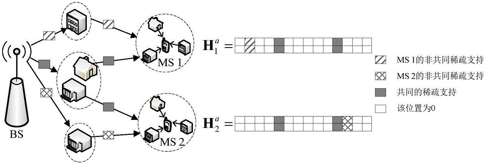
[0050] figure 1 A schematic diagram of a multi-user massive MIMO channel.
[0051] Assuming that the number of users is K=20, the base station and the user end are respectively configured with a uniform linear array (ULA), and the number of antennas of the base station is N=160, and the number of antennas of each user is the same and M=2. Assuming that the number of sparse supports (sparseness) of each user channel is the same and S=15, the common number of sparse supports Sc=8.
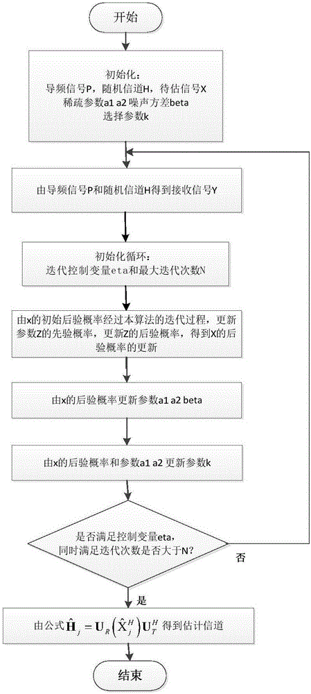
[0052] figure 2 It is a flow chart of multi-user massive MIMO channel estimation. According to the flow chart, the above parameters can be used to simulate the algorithm.
[0053] S1. Initialization, specifically:
[0054] S11, BS uses T time slots to broadcast T pilot signals X to 20 MSs P =[x (1) ,x (2) ,...,x (T) ]∈C N×T , where the number of antennas N of the BS is taken as...
PUM
 Abstract
Description
Claims
Application Information