
Inspection device, installation device, and inspecting method

An inspection device and image technology, applied in the direction of electrical components, electrical components, etc., can solve the problems of text disappearance, the inability to obtain the brightness difference of the image before loading, etc., and achieve the effect of high-precision inspection

Active Publication Date: 2017-02-22
JUKI CORP
View PDF4 Cites 2 Cited by
  • Summary
  • Abstract
  • Description
  • Claims
  • Application Information

AI Technical Summary

Problems solved by technology

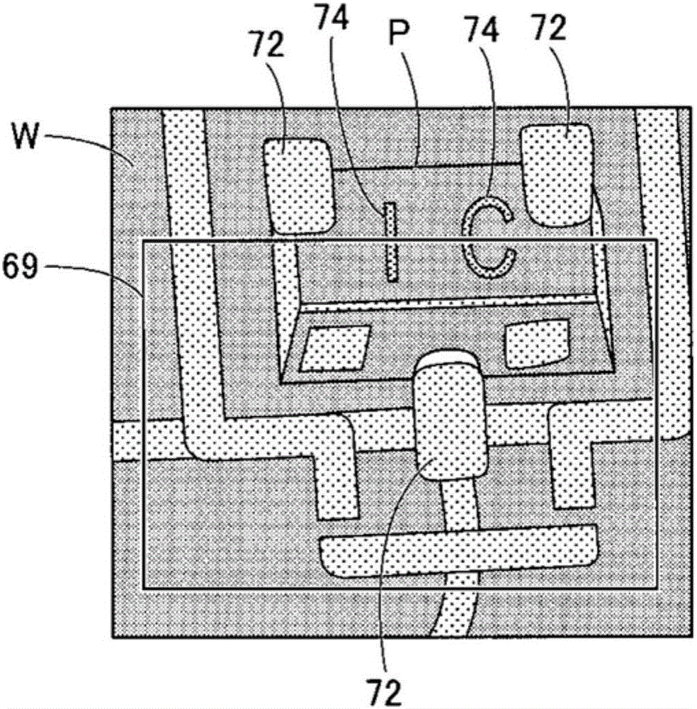
However, if the text printed on the body of the part is light or thin, the text will disappear from the body of the part due to the noise cutout performed on the mounted image
Therefore, a sufficient brightness difference between the before-mount image and the after-mount image cannot be obtained, and it may be misjudged that no part is mounted even though the part is mounted on the mounting surface of the board.

Method used


Image

  • Inspection device, installation device, and inspecting method
  • Inspection device, installation device, and inspecting method
  • Inspection device, installation device, and inspecting method

Examples


Embodiment Construction

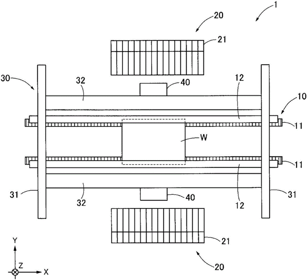
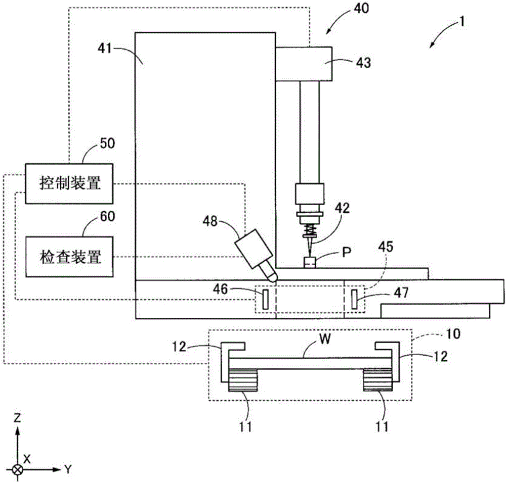
[0040] Next, the mounting device according to this embodiment will be described with reference to the drawings. figure 1 It is a schematic diagram which shows the whole mounting apparatus concerning this embodiment. figure 2 It is a schematic diagram which shows the periphery of the mounting head concerning this embodiment. 3 is a diagram showing an example of a pre-mounted image and a post-mounted image of a component according to a comparative example. In addition, the attachment device which concerns on this embodiment is just an example, and can be changed suitably.

[0041] Such as figure 1 As shown, the mounting device 1 is configured to supply parts P supplied from a parts supply unit 20 such as a tape feeder (see figure 2 ), is mounted on the mounting surface of the substrate W by a pair of mounting heads 40 . Wiring patterns, electrode pads, and the like are provided on the surface of the substrate W, and solder paste for bonding to terminals of the component P ...


PUM


Abstract

Whether a component is mounted on a substrate is inspected with high precision by simple processing. An inspection apparatus (60) inspects whether the component is mounted based on a pre-mounting image and a post-mounting image of the component taken before and after the component is mounted on a mounting surface of the substrate. The inspection device comprises a threshold setting section (62) for setting a threshold capable of recognizing the substrate according to the brightness value of the pre-mounting image; and a mask image generating section (63) for generating a mask image masking other than the substrate from the pre-mounting image according to the threshold. The specific areas corresponding to the mounting surface of the substrate of the pre-mounting image and the post-mounting image are compared with each other by employing the mask image, thereby inspecting whether the component is mounted or not.

Description

technical field [0001] The present invention relates to an inspection device, a mounting device, and an inspection method for inspecting whether or not a component is mounted on a substrate. Background technique [0002] As a mounting device, a mounting device including an inspection device for inspecting whether or not a component is mounted on a substrate is known using an imaging device mounted on a mounting head (for example, refer to Patent Document 1). In the inspection device described in Patent Document 1, the mounting surface of the board is photographed before and after the mounting of the parts, and the brightness difference between the pre-mounting image and the post-mounting image is obtained, thereby inspecting whether a part is mounted on the board mounting area. . In the inspection using the difference in luminance before and after mounting as described above, the difference in luminance in parts other than the components may have an influence. Therefore, n...

Claims


Application Information

Patent Timeline
Patent Type & Authority Applications(China)
IPC IPC(8): H05K13/08H05K13/04
CPCH05K13/0408H05K13/08
Inventor 中西由佳今野贵史
Owner JUKI CORP
Learn More