
Pneumatic radial tire for use on passenger vehicle

A technology for radial tires and passenger cars, applied in road tires, special tires, tire parts, etc., can solve the problems of increased tire weight, increased air resistance, increased vehicle resistance, etc., to improve wet road performance. and rolling resistance performance

Active Publication Date: 2017-02-22
BRIDGESTONE CORP
View PDF10 Cites 12 Cited by
  • Summary
  • Abstract
  • Description
  • Claims
  • Application Information

AI Technical Summary

Problems solved by technology

However, increasing the diameter and width of the tire leads to an increase in tire weight and air resistance, and thus increases vehicle resistance, and further, the load capacity of the tire becomes excessive

Method used


Image

  • Pneumatic radial tire for use on passenger vehicle
  • Pneumatic radial tire for use on passenger vehicle
  • Pneumatic radial tire for use on passenger vehicle

Examples


Embodiment 1

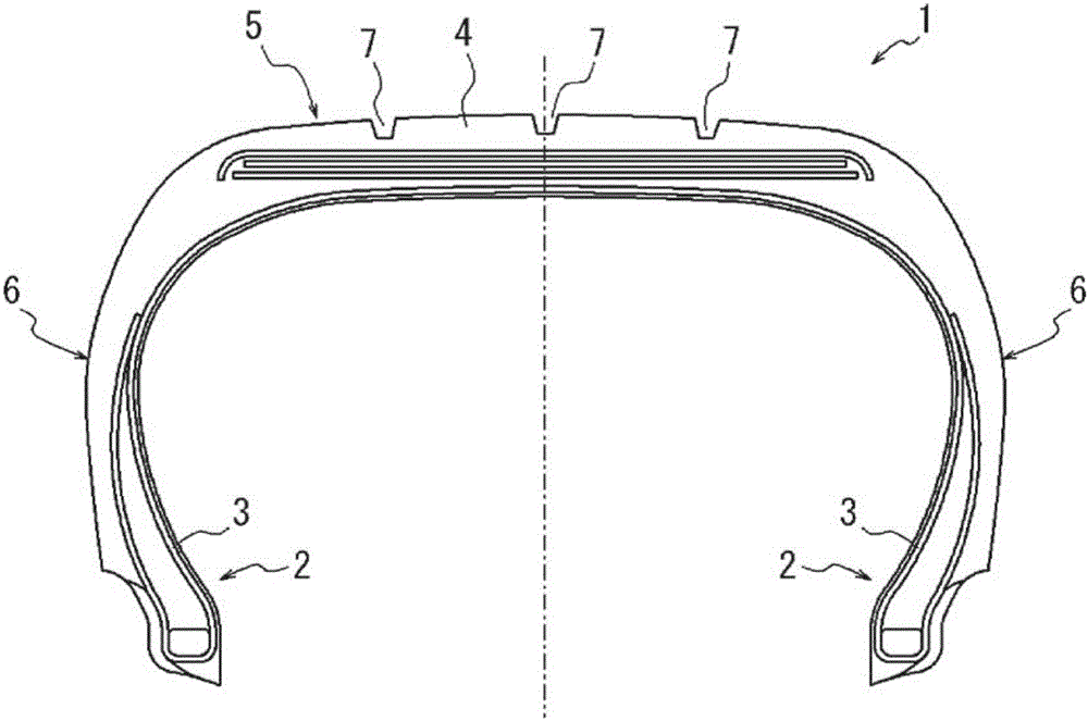
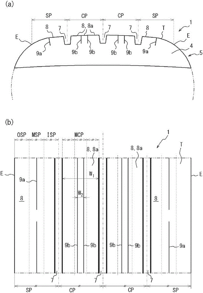
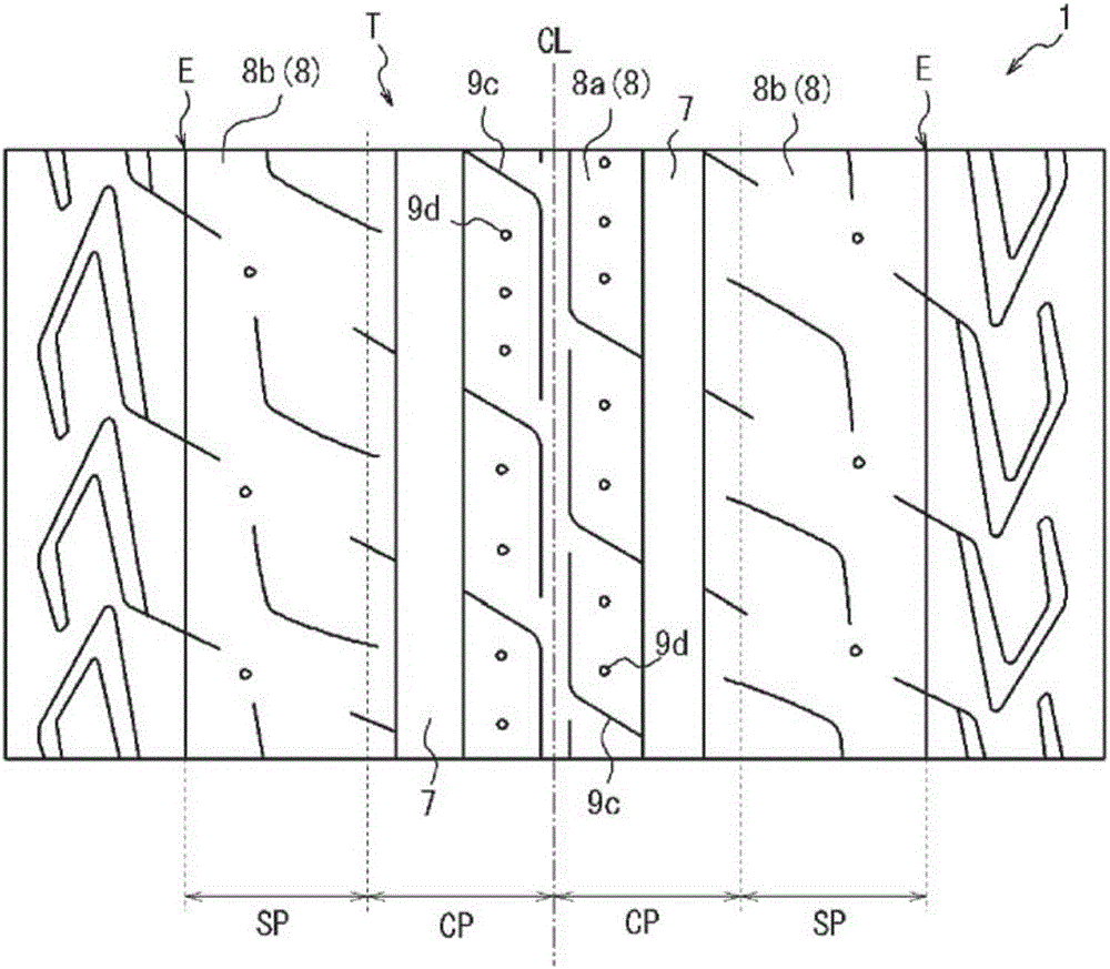
[0201] The tire of Example 1 is figure 1 with figure 2 The tire shown is a tire of size 165 / 60R19 and has the construction shown in Table 1. Furthermore, in the tire of Example 1, the tread surface had three circumferential main grooves (having a groove width of 7.5 mm) arranged at the boundary between the two central portions and at the boundary between each central portion and each shoulder portion. The circumferential main groove). In the tire of Example 1, the central circumferential sipe was not arranged, and the width of the tread surface in the tire width direction was 125 mm. In addition, the shoulder circumferential sipes are arranged to have a width of 0.7 mm.

[0202] The tires of Example 2 to Example 8 were the same as those of Example 1 with the same tires.

[0203] The tire of Example 9 was the same as the tire of Example 1 except that two central circumferential sipes continuous in the tire circumferential direction were arranged side by side in the tire c...

Embodiment 1 to Embodiment 12

[0212] Example 1 to Example 12, Comparative Example 3 to Comparative Example 7: rim size 5.5J19, internal pressure 300kPa


PUM

PropertyMeasurementUnit
Dynamic storage modulusaaaaaaaaaa

Abstract

The invention relates to a pneumatic radial tire for use on a passenger vehicle. The purpose of the present invention is to improve wet performance and rolling resistance performance in a radial tire of low width and high diameter. When the tire is assembled on a rim and the internal pressure is 250 kPa or greater, the ratio (SW / OD) between the tire cross-sectional width (SW) and the outside diameter (OD) (mm) is 0.26 or less when the tire cross-sectional width (SW) is less than 165 (mm), the tire cross-sectional width (SW) and the outside diameter (OD) (mm) satisfy the relational expression 2.135 X SW + 282.3 <= OD when the tire cross-sectional width (SW) is 165 (mm) or greater, the tread rubber has a dynamic storage modulus (E') at 30 DEG C of 6.0 to 12.0 MPa and a loss tangent (tan[delta]) at 60 DEG C of 0.05 to 0.15, and when the tread surface is equally divided into four areas in the tire width direction, the two inward areas in the tire width direction being center parts and the two outward areas in the tire width direction being shoulder parts, shoulder circumferential sipes that extend in the tire circumferential direction are located in the shoulder parts.

Description

technical field [0001] The present invention relates to a pneumatic radial tire for passenger vehicles. Background technique [0002] Since conventional vehicles built around 1960 were light in weight and the required cruising speeds of the vehicles were lower, the tires were less burdened. Therefore, bias tires with narrower tire section widths are used. However, currently, as vehicles become heavier and faster, tires have had radial structures and wider widths (for example, Patent Document 1). [0003] However, an increase in tire section width compresses the vehicle space and reduces ride comfort in the vehicle. In addition, fuel consumption may deteriorate due to an increase in air resistance. [0004] In recent years, due to increasing attention to environmental issues, the demand for better fuel consumption has become more and more urgent. Fuel efficiency is evaluated by rolling resistance (RR (rolling resistance)), and it is known that the lower the rolling resist...

Claims


Application Information

Patent Timeline
IPC IPC(8): B60C11/12B60C3/04B60C11/00B60C11/01B60C11/03
CPCB60C3/04B60C11/04B60C11/1236B60C17/0009B60C2011/0025B60C2017/0054B60C2200/04Y02T10/86
Inventor 畠中慎太郎桑山勲
Owner BRIDGESTONE CORP
Learn More