
Method for operating a gas turbine engine unit

A technology of gas turbine and engine, which is applied in the direction of engine components, engine cooling, gas turbine device, etc., which can solve the problems of large power consumption, large floor space, and high cost, and achieve the effect of cost saving

Inactive Publication Date: 2017-02-22
SIEMENS AG
View PDF8 Cites 2 Cited by
  • Summary
  • Abstract
  • Description
  • Claims
  • Application Information

AI Technical Summary

Problems solved by technology

In addition, large-scale air separation for oxygen production is currently performed through cryogenic processing, which is costly, takes up a lot of space, and consumes a lot of electricity

Method used


Image

  • Method for operating a gas turbine engine unit
  • Method for operating a gas turbine engine unit
  • Method for operating a gas turbine engine unit

Examples


Embodiment Construction

[0042] The terms upstream and downstream refer to the direction of flow of air flow and / or working gas flow through gas turbine engine 12 , unless otherwise indicated. If used and not specified otherwise, the terms axial, radial and circumferential refer to the axis of rotation 52 of the gas turbine engine 12 .

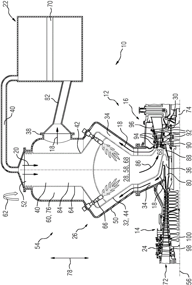
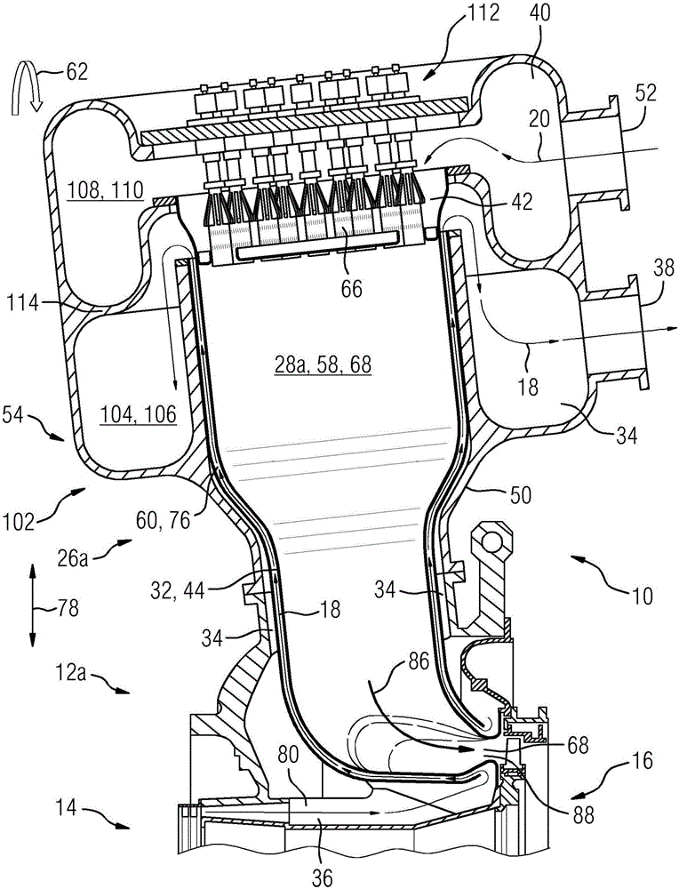
[0043] figure 1 An example of a gas turbine engine unit 10 having a gas turbine engine 12 and a unit 22 for oxygen extraction processing is shown in cross-section. The gas turbine engine 12 includes an air inlet 72 (not shown in detail) and a compressor section 14 with a compressor 24, a combustion section 26, and a turbine section 16 with a turbine 30, in order of flow of working fluids 18, 20, except All outside of the combustion section 26 generally in the direction of the longitudinal or rotational axis 56 are arranged in flow sequence. Gas turbine engine 12 further includes a shaft 74 rotatable about axis of rotation 56 and extending longitudinally through gas ...


PUM


Abstract

The present invention relates to a method for operating a gas turbine engine unit (10) comprising a gas turbine engine (12, 12a, 12b, 12c) with at least a compressor section (14) and a turbine section (16), wherein the compressor section (14) and the turbine section (16) are operable by a working fluid (18, 20), and further comprising a unit (22) for an oxygen extraction process, wherein the method comprises the steps of: Discharging a total amount of O2-rich working fluid (18) from a compressor (24) of the compressor section (14) to the unit (22) for the oxygen extraction process and extracting O2 from the O2-rich working fluid (18) by an oxygen extraction process.

Description

technical field [0001] The invention relates to a method for operating a gas turbine engine unit comprising a gas turbine engine having at least a compressor section and a turbine section, wherein the compressor section and the turbine section are operable by a working fluid, and the gas turbine The engine unit also includes a unit for oxygen extraction processing. The invention also relates to a gas turbine engine unit implemented to carry out the inventive method. Background technique [0002] In the gas turbine engine, the working fluid compressed by the compressor enters the combustor section, and combustion of the mixture of the working fluid and fuel takes place in the combustion device. The resulting combustion gases drive the turbine by means of expansion and deflection of the gases passing through the turbine of the gas turbine engine. Turbine work, or a portion thereof, is transmitted to the compressor through an interconnecting shaft. It is important to make th...

Claims


Application Information

Patent Timeline
Patent Type & Authority Applications(China)
IPC IPC(8): F02C6/08F02C7/08F02C7/18B01D53/22
CPCB01D53/228F02C6/08F02C7/08F02C7/18B01D53/22B01D2256/12F02C3/28F05D2260/205
Inventor O·林德曼M·斯乔丁
Owner SIEMENS AG
Learn More