Fuel feed system to a fuel injector, and fuel injector

A technology of fuel supply device and fuel injector, which is applied in the direction of fuel injection device, charging system, sealing of engine, etc.

Active Publication Date: 2017-02-22
ROBERT BOSCH GMBH
View PDF6 Cites 3 Cited by
  • Summary
  • Abstract
  • Description
  • Claims
  • Application Information

AI Technical Summary

Problems solved by technology

Such a sealing element, which may even be available as a standard or universal part, surprisingly solves the problem of the required tightness and also enables a particularly simple and thus cost-effective construction in the connection area Pressure connection or injector housing

Method used


Image

  • Fuel feed system to a fuel injector, and fuel injector
  • Fuel feed system to a fuel injector, and fuel injector
  • Fuel feed system to a fuel injector, and fuel injector

Examples


Embodiment Construction

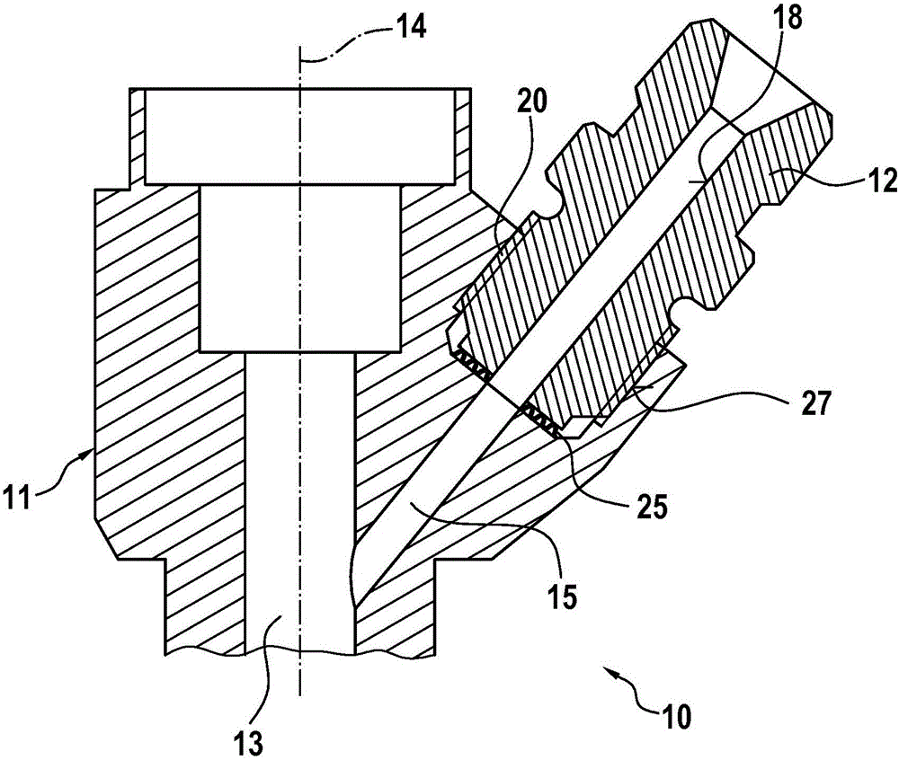
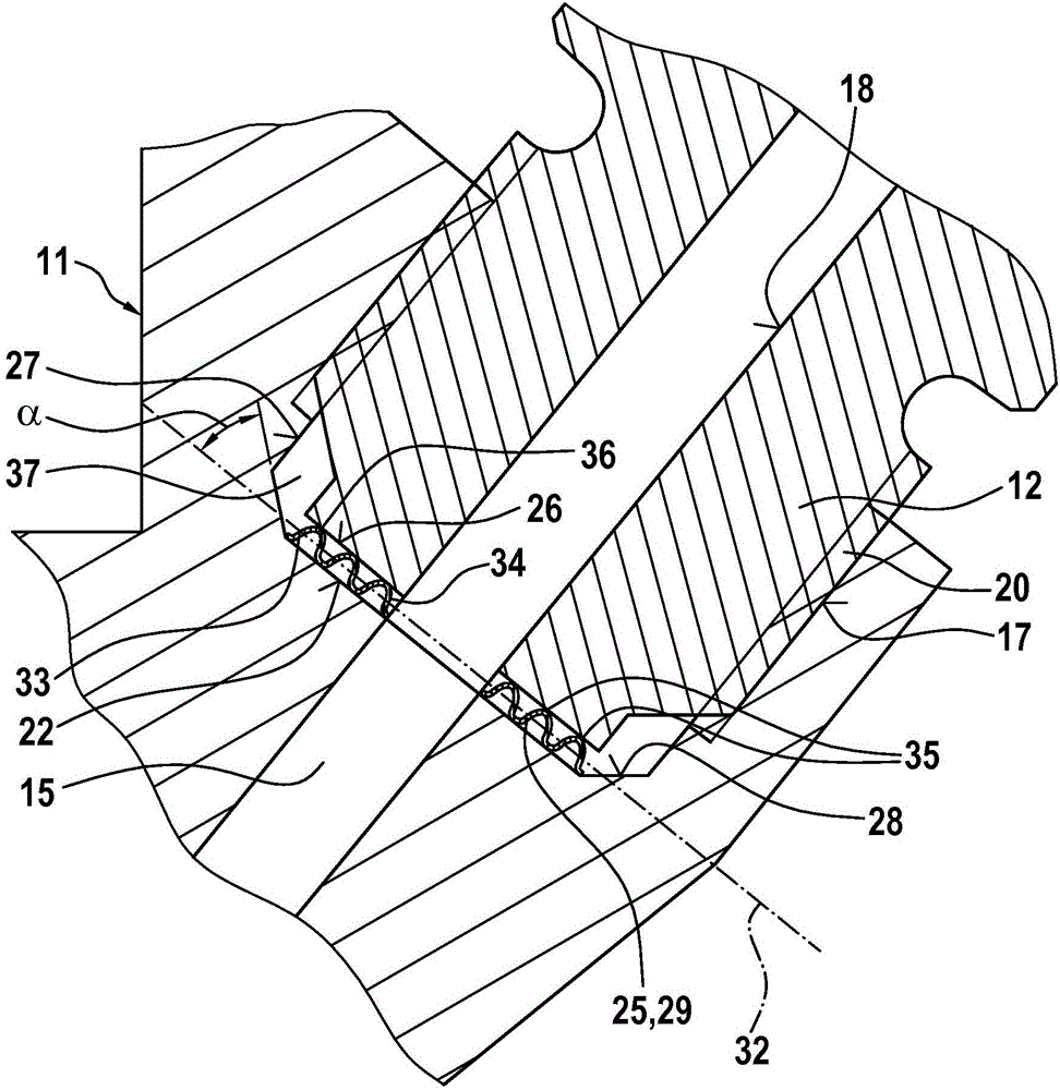
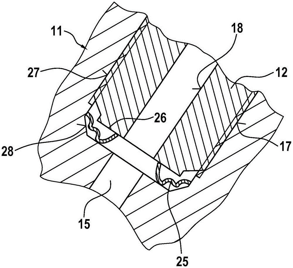
[0019] exist Figures 1 to 3 The connection region according to the invention between the injector housing 11 and the pressure connection 12 of the fuel injector 10 is depicted in . The fuel injector 10 is in particular a so-called common rail injector, which is designed to supply fuel to a combustion chamber of an internal combustion engine (not shown) at system pressures above 2000 bar. For this purpose, the injector housing 11 made of steel has a partly shown high-pressure chamber 13 in which a not-shown nozzle needle arrangement is movable back and forth. By controlling the reciprocating movement of the nozzle needle, the fuel is discharged in the desired manner through at least one injection opening formed in the injector housing 11 into the combustion chamber. The high-pressure chamber 13 is supplied with high-pressure (system pressure) fuel via a supply channel 15 arranged obliquely with respect to the longitudinal axis 14 of the injector housing 11 . For this purpose...


PUM


Abstract

The invention relates to a fuel feed system to a fuel injector (10), said system comprising a pressure port (12) which is connected to an injector housing (11), and which has a through-hole (18) for fuel, said through-hole entering on the side of the injector housing (11) in the region of a front end (26) of the pressure port (12) and running in a longitudinal direction of the pressure port (12), and said through-hole being arranged such that, in an assembled state, it aligns with a supply channel (15) running in the injector housing (11), wherein the injector housing (11) has a receiving means (17) in the form of a blind hole for the end region of the pressure port (12) facing the injector housing (11), and wherein the pressure port (12) is connected to the injector housing (11), against a base (22) of the receiving means (17), in a pressure-tight manner, by axially inserting a sealing element (25) having a through opening (30) for the fuel.

Description

technical field [0001] The invention relates to a fuel supply device for supplying fuel to a fuel injector according to the preamble of claim 1 . The invention also relates to a fuel injector with a fuel supply device according to the invention. Background technique [0002] A fuel supply device according to the preamble of claim 1 is known from DE 102 49 142 A1 of the applicant. The problem with this type of fuel supply device is that, in the assembled state of the fuel injector, the necessary seal is established between the injector housing and the fuel nipple of the fuel injector in order to allow the flow through the pressure nipple into the injector housing. The fuel, which may have a pressure of more than 2000 bar, does not leave the connecting region between the pressure connection and the injector housing. For this purpose, in DE 102 49 142 A1 a flat sealing ring is used as the sealing element, which is connected to the pressure connection by means of a specific sh...

Claims


Application Information

Patent Timeline
Patent Type & Authority Applications(China)
IPC IPC(8): F02M55/00F16J15/08
CPCF02M55/005F16J15/0887
Inventor S·莱泽尔H·拉利克
Owner ROBERT BOSCH GMBH
Why Eureka
Try Eureka