
Metal-air battery

A metal-air battery and battery technology, which is applied in the direction of batteries, fuel cells, battery electrodes, etc., can solve complex power supply control and other problems, and achieve the effect of improving flow cycle and prolonging service life

Active Publication Date: 2017-02-22
MAHLE INT GMBH
View PDF19 Cites 9 Cited by
  • Summary
  • Abstract
  • Description
  • Claims
  • Application Information

AI Technical Summary

Problems solved by technology

Therefore, complex power control, for example together with a battery as a power buffer, is usually required

Method used


Image

  • Metal-air battery
  • Metal-air battery

Examples


Embodiment Construction

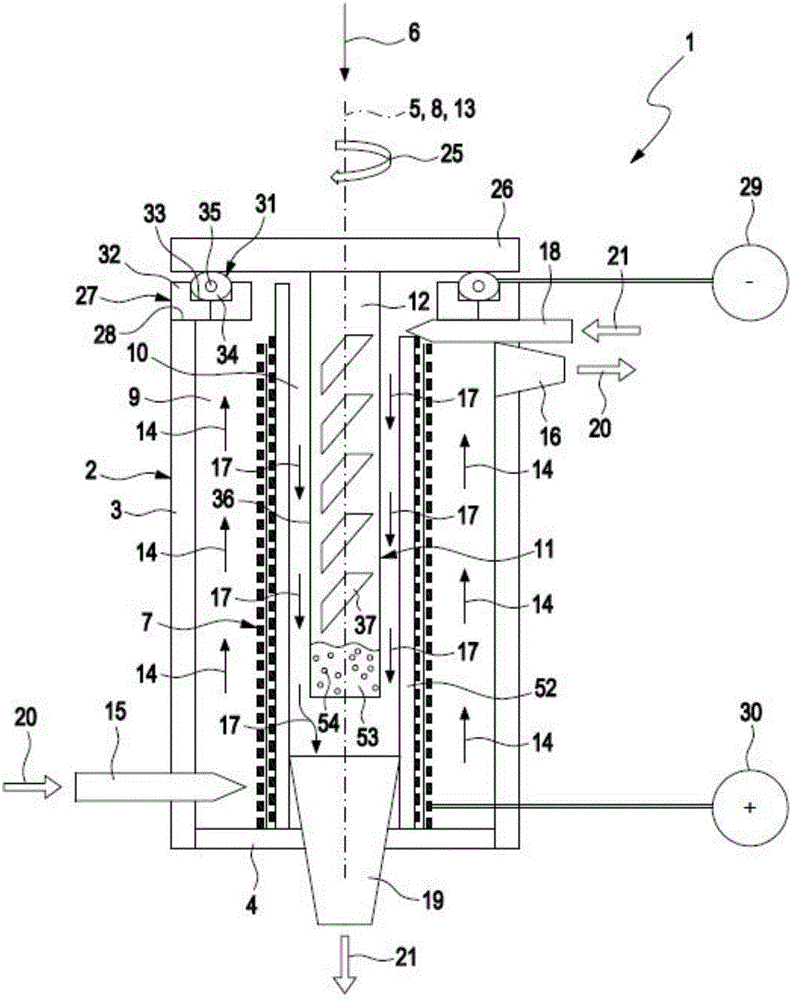
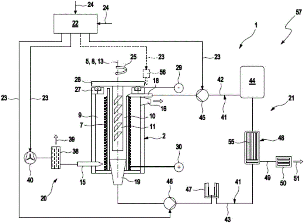
[0068] corresponds to figure 1 and figure 2 A metal-air cell 1 , preferably an aluminum-air cell, comprises a casing 2 that is electrically insulating and preferably consists of an electrically insulating material such as plastic. In the example shown, the housing 2 is designed as a cylindrical container and comprises a cylindrical housing 3 and a plate-shaped, in particular circular, bottom 4 . In the installed state or operational readiness of the metal-air battery 1 , which can also be described abbreviatedly below as a battery, the casing 2 is arranged so that the longitudinal central axis 5 of the casing 2 is oriented substantially vertically, ie substantially parallel to exist figure 1 The direction of gravity 6 indicated by the arrow in . The battery 1 also comprises at least one hollow cylindrical cathode 7 , preferably arranged in the housing so that the longitudinal center axis 8 of the cathode 7 extends substantially parallel to the direction of gravity 6 in the...


PUM


Abstract

The invention relates to a metal-air battery (1), comprising a housing (2), a hollow cylindrical cathode (7), which is arranged between an air chamber (9) and an electrolyte chamber (10) in the housing (2), a metal anode (11), which is arranged in the electrolyte chamber (10), an air path (14) leading through the housing (2), which air path leads from an air inlet (15) of the housing (2) to an air outlet (16) of the housing (2), an air supply device (20) for producing an air flow, which follows the air path (14) and impinges on the cathode (7), an electrolyte path (17) leading through the housing (2), which electrolyte path leads from an electrolyte inlet (18) of the housing (2), said electrolyte inlet being fluidically connected to the electrolyte chamber (10), to an electrolyte outlet (19) of the housing (2), said electrolyte outlet being fluidically connected to the electrolyte chamber (10), and an electrolyte supply device (21) for producing an electrolyte flow, which follows the electrolyte path (17) and impinges on the anode (11) and the cathode (7).

Description

technical field [0001] The present invention relates to metal-air batteries, in particular to aluminum-air batteries. The invention also relates to a battery system comprising at least two such batteries. Furthermore, the invention relates to an electric motor equipped vehicle equipped with at least one such battery or at least one such battery system. Finally, the invention relates to a method of operating such a battery. Background technique [0002] Metal-gas batteries are generally primary batteries, ie non-rechargeable galvanic cells, which develop a specific voltage by chemical reaction of the corresponding metal with air oxidation. Such primary cells can also be referred to as fuel cells. In contrast to primary batteries, secondary batteries, so-called accumulators, are rechargeable. [0003] An exemplary structure for a zinc-air battery is known from WO 2012 / 156972 A1. [0004] Zinc electrodes for repeated use in rechargeable batteries are known from WO 2013 / 150...

Claims


Application Information

Patent Timeline
IPC IPC(8): H01M2/08H01M2/30H01M2/40H01M6/50H01M10/42H01M4/02H01M4/38H01M4/46H01M16/00H01M50/55H01M50/77
CPCH01M6/5022H01M6/5038H01M10/425H01M2220/20H01M2300/0014H01M2004/025H01M16/006H01M6/5077H01M4/463H01M4/381H01M50/77H01M50/55B60L58/10H01M4/661H01M12/08H01M2300/0002B60L50/70Y02E60/10Y02T90/40Y02T10/70Y02E60/50H01M8/04089H01M8/0662H01M12/06H01M50/183
Inventor 彼得·恩勒特
Owner MAHLE INT GMBH
Learn More