Automatic glue injection system and porous insertion core module manufacturing method

A ferrule and glue injection technology, which is applied to the coupling of optical components, optical waveguides, light guides, etc., can solve the problems of low efficiency, difficulty in accurately controlling the amount of glue injected, and reduce the optical performance of ferrule components, so as to improve the efficiency of glue injection , Precise amount of glue injection, improve the effect of manufacturing quality

Active Publication Date: 2017-03-01
TYCO ELECTRONICS (SHANGHAI) CO LTD +2
View PDF4 Cites 3 Cited by
  • Summary
  • Abstract
  • Description
  • Claims
  • Application Information

AI Technical Summary

Problems solved by technology

[0003] In the prior art, the manual method is generally used to inject glue into the ferrule. The efficiency of manual glue injection is low, and it is difficult to accurately control the amount of glue injected, which affects the manufacturing quality of the ferrule assembly and reduces the optical performance of the ferrule assembly.

Method used


Image

  • Automatic glue injection system and porous insertion core module manufacturing method
  • Automatic glue injection system and porous insertion core module manufacturing method
  • Automatic glue injection system and porous insertion core module manufacturing method

Examples


Embodiment Construction

[0038] The technical solutions of the present invention will be further specifically described below through the embodiments and in conjunction with the accompanying drawings. In the specification, the same or similar reference numerals designate the same or similar components. The following description of the embodiments of the present invention with reference to the accompanying drawings is intended to explain the general inventive concept of the present invention, and should not be construed as a limitation of the present invention.

[0039] In addition, in the following detailed description, for purposes of explanation, numerous specific details are set forth in order to provide a comprehensive understanding of the embodiments of the present disclosure. It may be evident, however, that one or more embodiments may be practiced without these specific details. In other instances, well-known structures and devices are shown in diagrammatic form to simplify the drawings.

[0...


PUM


Abstract

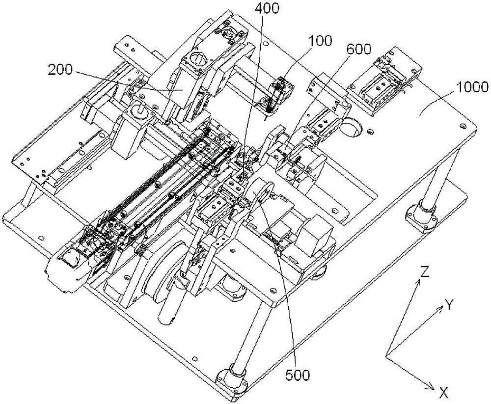
The invention discloses an automatic glue injection system, and the system comprises a glue injector which is used for injecting glue into a porous insertion core; a first insertion core clamping tool which is used for clamping the porous insertion core, so as to enable the porous insertion core to remain at a first glue injection position; and a second insertion core clamping tool which is used for clamping the porous insertion core, so as to enable the porous insertion core to remain at a second glue injection position. At the first glue injection position, no optical fiber is inserted into an optical fiber jack of the porous insertion core, and the glue injector injects the glue into the porous insertion core, in which no optical fiber is inserted, till the whole optical fiber jack is filled with glue. At the second glue injection position, the optical fiber is inserted into the optical fiber jack of the porous insertion core, and the glue injector injects glue into the porous insertion core with the optical fiber again, so as to compensate the glue lost in the insertion process of the optical fiber. According to the invention, the system can automatically inject glue into the optical fiber jack of the porous insertion core, improves the glue injection efficiency, and improves the manufacturing quality of a porous insertion core module.

Description

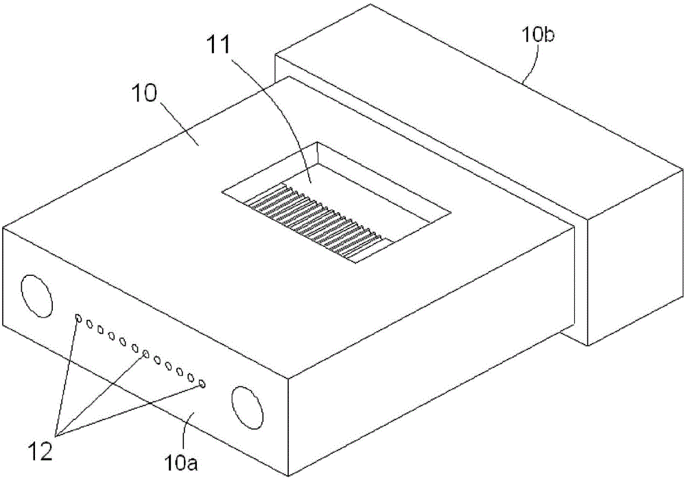
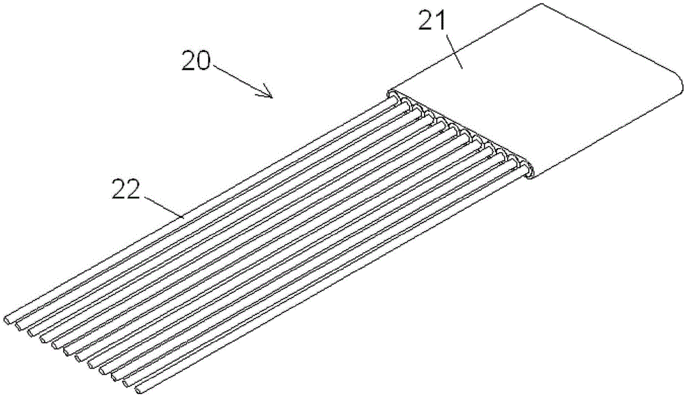
technical field [0001] The invention relates to an automatic glue injection system for injecting glue into an optical fiber insertion hole of a porous ferrule and a manufacturing method of a porous ferrule assembly. Background technique [0002] A fiber optic connector generally includes a housing and a ferrule assembly assembled in the housing. The ferrule assembly includes a ferrule and an optical fiber inserted into an optical fiber socket of the ferrule. In the prior art, manufacturing a ferrule assembly generally includes the following steps: First, inject glue (or called adhesive) into the ferrule until the glue fills the entire optical fiber insertion hole; then, insert the optical fiber into the ferrule that has been filled glue in the fiber jack; finally, the glue is heated to cure, thereby securing the fiber in the ferrule. This produces a ferrule assembly. [0003] In the prior art, glue is generally injected into the ferrule manually. The efficiency of manual ...

Claims


Application Information

Patent Timeline
IPC IPC(8): G02B6/38
CPCG02B6/3802G02B6/3803G02B6/3885G02B6/3861G02B6/3843G02B6/3866G02B6/4226
Inventor 谢逢春曾庆龙张雨张丹丹胡绿海鲁異
Owner TYCO ELECTRONICS (SHANGHAI) CO LTD
Why Eureka
Try Eureka