
Electronic package and fabrication method thereof

A technology of electronic packaging and manufacturing method, which is applied in the direction of circuits, electrical components, electrical solid devices, etc., can solve the problems of defective products, unable to remove gas, etc., and achieve the effect of avoiding gas explosion

Active Publication Date: 2017-03-01
SILICONWARE PRECISION IND CO LTD
View PDF5 Cites 6 Cited by
  • Summary
  • Abstract
  • Description
  • Claims
  • Application Information

AI Technical Summary

Problems solved by technology

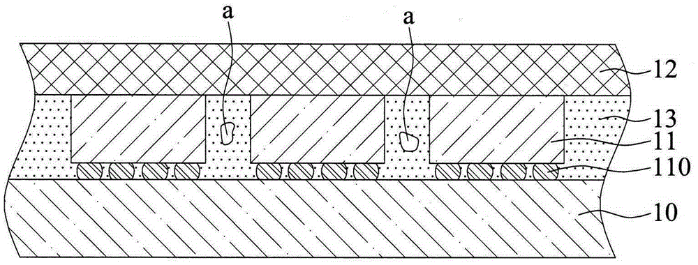
[0008] However, the material of the encapsulation layer 13 includes not only epoxy resin, but also various solvents (solvents) (such as hardeners, fillers, catalysts, and release agents), and in an environment with a temperature above 200° C., the above-mentioned various The solvent will gradually decompose into gas. At this time, because the cover plate 12 and the silicon interposer 10 block the upper and lower sides of the encapsulation layer 13, the gas cannot be removed, so the gas will exist in the encapsulation layer 13 And the bubble a is formed, so that when another high-temperature manufacturing method is carried out, such as the product terminal manufacturing method using surface mount technology (SMT), the bubble a will expand due to heat and explode, resulting in defective products

Method used


Image

  • Electronic package and fabrication method thereof
  • Electronic package and fabrication method thereof
  • Electronic package and fabrication method thereof

Examples


Embodiment Construction

[0050] Embodiments of the present invention are described below through specific examples, and those skilled in the art can easily understand other advantages and effects of the present invention from the content disclosed in this specification.

[0051] It should be noted that the structures, proportions, sizes, etc. shown in the drawings attached to this specification are only used to match the content disclosed in the specification for the understanding and reading of those skilled in the art, and are not intended to limit the implementation of the present invention. Limiting conditions, so there is no technical substantive meaning, any modification of structure, change of proportional relationship or adjustment of size, without affecting the effect and purpose of the present invention, should still fall within the scope of the present invention. The disclosed technical content must be within the scope covered. At the same time, terms such as "above", "first", "second" and ...


PUM


Abstract

The invention discloses an electronic package and a fabrication method thereof. The fabrication method comprises the steps of: providing an interposer having a plurality of conductive vias and at least an opening formed at a periphery of the conductive vias; disposing at least an electronic element on the interposer; and bonding a cover plate to the electronic element and forming an encapsulant between the cover plate and the interposer so as to encapsulate the electronic element and fill the opening, thus allowing the encapsulant in the opening to come into contact with air. As such, during a subsequent high temperature process, evaporated solvents can flow out of the encapsulant through the opening without forming bubbles in the encapsulant, thereby preventing a bubble explosion from occurring..

Description

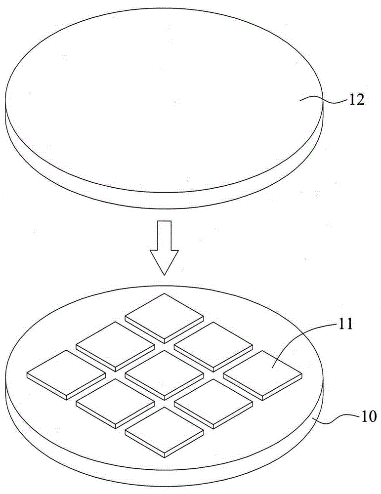
technical field [0001] The present invention relates to a packaging manufacturing method, in particular to an electronic packaging structure and a manufacturing method thereof for improving the reliability of the manufacturing method. Background technique [0002] With the vigorous development of the electronic industry, electronic products are gradually moving towards the trend of multi-function and high performance. Technologies currently used in the field of chip packaging, such as Chip Scale Package (CSP for short), Direct Chip Attached (DCA for short) or Multi-Chip Module (MCM for short) ) and other flip-chip packaging modules, or three-dimensional stacking of chips into three-dimensional integrated circuit (3D IC) chip stacking technology, etc. [0003] Figure 1A to Figure 1B It is a schematic diagram of the manufacturing method of the conventional semiconductor package 1 . [0004] Such as Figure 1A As shown, a cover plate 12 and a silicon interposer (TSI) 10 hav...

Claims


Application Information

Patent Timeline
Patent Type & Authority Applications(China)
IPC IPC(8): H01L23/522H01L23/31H01L21/50
CPCH01L2224/16225H01L2924/15311H01L2924/18161H01L23/3128H01L21/568H01L21/6835H01L2221/68331H01L23/49827H01L23/49833H01L21/561H01L23/3121H01L21/78
Inventor 梁芳瑜张宏宪赖顗喆
Owner SILICONWARE PRECISION IND CO LTD
Learn More