Vacuum fish pump floating on water

A vacuum suction and fish pump technology, applied in fishing, application, animal husbandry, etc., can solve the problems of rising damage rate of live fish, affecting the circulation of live fish, uncoordinated valve control, etc. Effects of fish quality and suction power

Active Publication Date: 2017-03-08
FISHERY MACHINERY & INSTR RES INST CHINESE ACADEMY OF FISHERY SCI
View PDF5 Cites 5 Cited by
  • Summary
  • Abstract
  • Description
  • Claims
  • Application Information

AI Technical Summary

Problems solved by technology

[0004] When the above-mentioned vacuum fish suction pump is sucking, the control of the valve parts is uncoordinated, the time difference between the opening of the valve parts and the flow of air flow, bleeding on the surface of the fish body after being sucked, severe cases vomiting blood in the mouth, and some are also affected by the valve parts being closed. The shear damage affects the subsequent circulation of live fish; and, because the suction height is too high when the fish is sucked, and the vacuum negative pressure is greater than -0.05Mpa, the damage rate of the live fish rises obviously, and the suction energy is increased. consumption, and the ability of automatic control is complex
[0005] China's aquatic products are mainly fresh fish. Vacuum fish suction pumps are aimed at the use of large-scale aquaculture, such as: large-scale cage culture in coastal waters and lakes, including loading at the wharf. Live fish equipment, and the use of the current fish suction pump still has the above problems, which makes the use of the existing vacuum fish suction pump limited to a certain extent

Method used


Image

  • Vacuum fish pump floating on water
  • Vacuum fish pump floating on water
  • Vacuum fish pump floating on water

Examples


Embodiment Construction

[0040] The present invention will be further described below in conjunction with specific embodiments and accompanying drawings.

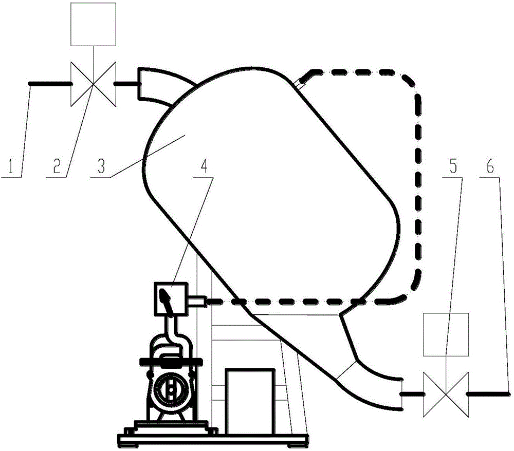
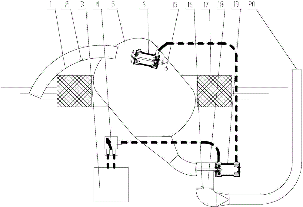
[0041] Such as figure 2 As shown, a vacuum suction fish pump floating on the water surface includes the following components:

[0042] float 17;

[0043] The fish tank 5 arranged on the floating body 17;

[0044] A fish suction pipe 1 communicated with the inlet of the fish tank 5;

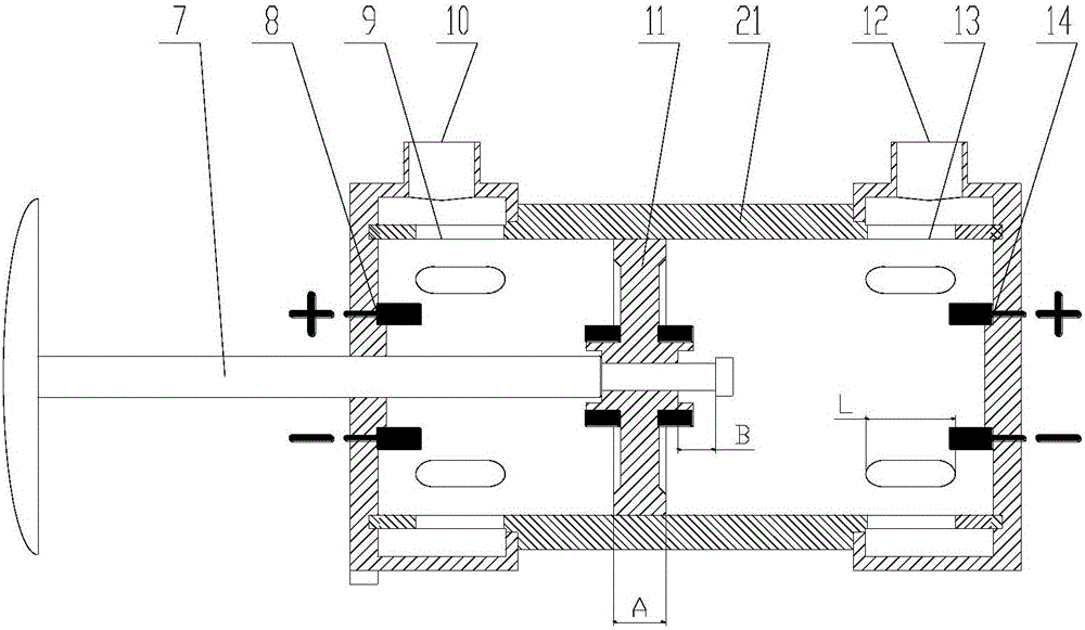
[0045] The first electromagnetic pilot pneumatic valve 6 arranged in the fish tank 5 near the entrance of the fish suction pipe 1 and the second electromagnetic pilot pneumatic valve 19 arranged outside the fish tank 5, the rear air port 12 of the first electromagnetic pilot pneumatic valve 6 It communicates with the rear air port 12 of the second electromagnetic pilot pneumatic valve 19;

[0046] The fish row transition chamber 18 is set on the valve plug connecting rod 7 of the second electromagnetic guiding pneumatic valve 19, and the inlet of the fish row tran...


PUM


Abstract

The invention relates to a vacuum fish pump floating on the water, and belongs to the field of fishery engineering. The vacuum fish pump floating on the water comprises a floating body, a fish tank arranged on the floating body, a fish suction pipe communicated with an inlet of the fish tank, a first electromagnetic piloted pneumatic valve arranged in the fish tank, a second electromagnetic piloted pneumatic valve arranged outside the fish tank, a discharged fish transition bin sleeving a valve plug connecting rod of the second electromagnetic piloted pneumatic valve, a vacuum pump, a four-way reversing valve and a liquid level control system, wherein a rear gas opening of the first electromagnetic piloted pneumatic valve is communicated with the rear gas opening of the second electromagnetic piloted pneumatic valve; an inlet of the discharged fish transition bin is communicated with an outlet of the fish tank; the outlet of the discharged fish transition bin is communicated with a fish conveying pipe; the inlet of the four-way reversing valve is communicated with the vacuum pump; the outlet of the four-way reversing valve is communicated with a front gas opening of the second electromagnetic piloted pneumatic valve. The vacuum fish pump provided by the invention reduces suction height of the fish pump, improves fish quality, and reduces operation energy consumption of equipment.

Description

technical field [0001] The invention relates to the field of fishery engineering, in particular to a vacuum fish suction pump floating on the water surface. Background technique [0002] China is a big country of aquatic product breeding. With the modernization of fishery, fish suction pumps have been put into use more and more as related supporting equipment for large-scale net cage fishing in reservoirs. At present, different styles of suction pumps have been developed at home and abroad. Fish pumps, such as submersible fish suction pumps, vacuum fish suction pumps, jet fish suction pumps, etc. The advantage of vacuum fish suction pumps is that the ratio of water to water can be as high as 1 / 1, which greatly improves the efficiency of fish suction and reduces operating costs. . [0003] Existing vacuum fish pumps, such as figure 1 As shown, the fish suction pipe 1 is connected with the first electric ball valve 2 and the fish tank 3, the outlet of the fish tank 3 is conn...

Claims


Application Information

Patent Timeline
Patent Type & Authority Applications(China)
IPC IPC(8): A01K79/00
CPCA01K79/00
Inventor 顾海涛陈寅杰石瑞何雅萍吴姗姗徐英士
Owner FISHERY MACHINERY & INSTR RES INST CHINESE ACADEMY OF FISHERY SCI
Why Eureka
Try Eureka