

A heat pump air conditioner unit, its control method and electric passenger car
A heat pump air conditioner and control method technology, which is applied to vehicle components, air handling equipment, heating/cooling equipment, etc., can solve problems such as indoor temperature reduction, and achieve the effect of improving system reliability
- Summary
- Abstract
- Description
- Claims
- Application Information
AI Technical Summary
Problems solved by technology
Method used
Image


Examples
specific Embodiment approach
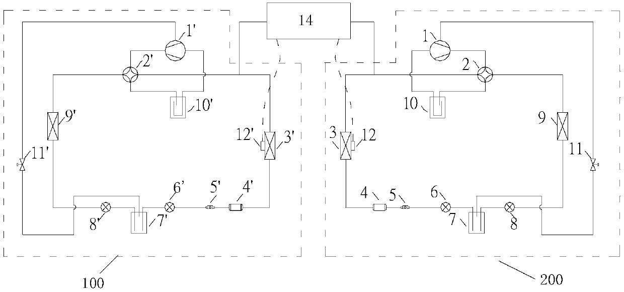
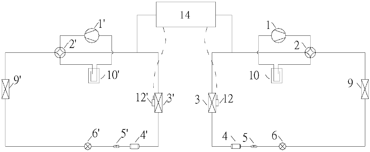
[0093] Among them, key parameters such as the operating parameters of the system, the opening and closing of air supply and ventilation solenoid valves, the adjustment of the throttle valve, the reading of the temperature sensor parameters, and whether defrosting or not are all controlled by the centralized control unit. The present invention proposes a pure electric passenger car air-conditioning system that can defrost in partitions. By setting up two sets of independent heat pump air-conditioning systems and using a centralized control unit, it is used for cooling and heating in the car, and when it is in a low-temperature environment, Sequentially defrost the left and right systems to ensure that at least one subsystem in the whole system is in normal heating mode. At this time, the hot air on one side can be sent to the other side through the connected air duct to meet the heat requirements in the car. comfort needs.
[0094] Option One:
[0095] figure 1 Shown is a sch...
PUM
 Abstract
Description
Claims
Application Information