Constant contact steel spring crack preventing method and vertical backstop
A vertical stopper and steel spring technology, applied in bogies, railway car body parts, axle box installation, etc., can solve the problem of greatly improving the fracture resistance of steel springs, it is difficult to effectively reduce the metal fatigue of steel springs, and there is no adjustment variable Rigidity and other issues to achieve the effect of compact structure, preventing steel spring breakage and reducing wear
- Summary
- Abstract
- Description
- Claims
- Application Information
AI Technical Summary
Problems solved by technology
Method used
Image

Examples
Embodiment 1
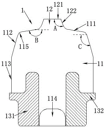
[0041] Such as Figure 5 As shown, a positioning base 4 is fixed above the axle box 5, and a double-volume spiral steel spring 2 is arranged above the positioning base 4, and the steel spring 2 supports the weight of the locomotive above the bogie frame 6. In order to reduce the vertical load borne by the steel spring 2 and reduce the metal fatigue generated by the steel spring 2 during locomotive operation, thereby preventing the steel spring 2 from breaking, a vertical stop 1 is provided in the steel spring 2 . The base flange 132 of the vertical stop 1 abuts against the positioning base 4 , and since the vertical stop 1 and the positioning base 4 are both revolving bodies, the vertical stop 1 can be stuck in the positioning base 4 . A frame guide cylinder 3 is arranged directly above the vertical stop 1. When the locomotive is unloaded, the rubber boss 12 of the vertical stop 1 is in contact with the frame guide cylinder 3, and the locomotive moves from no load to the maxim...
Embodiment 2
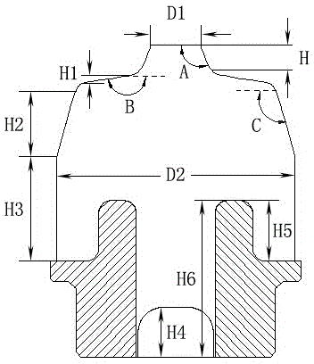
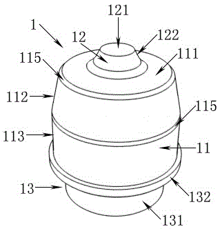
[0063] Such as Figure 6 As shown, the difference from Embodiment 1 is that the rotator-shaped rubber boss 12 above the rubber body 11 is no longer conical, but the generatrix 123 of the rotator-shaped rubber boss 12 is outward. Extruded smooth curves. Such as Figure 7 As shown, the diameter D3 of the rubber boss 12 refers to the diameter of the bottom of the rubber boss 12 , which is different from the diameter D1 of the rubber boss 12 in Embodiment 1, which refers to the diameter of the top of the rubber boss 12 . The preferred value of the diameter D3 of the rubber boss 12 in this embodiment is 20mm-60mm.
[0064] The busbar 123 is a gyratory-shaped rubber boss 12 protruding outwards with a smooth curve. When the locomotive load increases and the frame guide cylinder 3 is pressed down, the stiffness curve of the vertical stop 1 can be made smoother, thereby It can more effectively prevent the rigidity of the vertical stop 1 from increasing suddenly, and can better absor...
PUM
| Property | Measurement | Unit |
|---|---|---|
| Diameter | aaaaa | aaaaa |
| Height | aaaaa | aaaaa |
| Diameter | aaaaa | aaaaa |
Abstract
Description
Claims
Application Information
 - R&D
- Intellectual Property
- Life Sciences
- Materials
- Tech Scout
- Unparalleled Data Quality
- Higher Quality Content
- 60% Fewer Hallucinations
Browse by: Latest US Patents, China's latest patents, Technical Efficacy Thesaurus, Application Domain, Technology Topic, Popular Technical Reports.
© 2025 PatSnap. All rights reserved.Legal|Privacy policy|Modern Slavery Act Transparency Statement|Sitemap|About US| Contact US: help@patsnap.com