Casing pipe flexion induction support with bidirectional spiral induction unit

A two-way helical and casing technology, applied in the direction of building types, building components, earthquake resistance, etc., can solve the problems of weakening the energy dissipation capacity of supports, not conducive to the generation of plastic hinges, and low design flexibility, so as to achieve good axial bearing capacity, Avoid overall instability and ensure the quality of components

Active Publication Date: 2017-03-08
SOUTHEAST UNIV
View PDF8 Cites 2 Cited by
  • Summary
  • Abstract
  • Description
  • Claims
  • Application Information

AI Technical Summary

Problems solved by technology

On June 1, 2016, the applicant proposed an energy-dissipative buckling-constrained support with symmetrical initial defect units at the end (application number 201610383430.5) and a buckling-controlled support with diamond-shaped energy-dissipating units at the end (application No. 201610380804.8) has a fixed geometry and little design flexibility
Moreover, the thickness and structure of the energy-dissipating unit at the crease in the above support are the same as those at the non-crease, which is not conducive to the generation of plastic hinges at the crease.
In addition, these supports are composed of end restraint segments, buckling segments, and sleeves. The sleeves are on the outside of the buckling segment, and there is no support on the inside of the buckling segment, which is prone to low-order instability toward the inside, thereby weakening the energy dissipation capacity of the support.

Method used


Image

  • Casing pipe flexion induction support with bidirectional spiral induction unit
  • Casing pipe flexion induction support with bidirectional spiral induction unit
  • Casing pipe flexion induction support with bidirectional spiral induction unit

Examples


Embodiment Construction

[0029] The present invention will be further explained below in conjunction with the drawings.

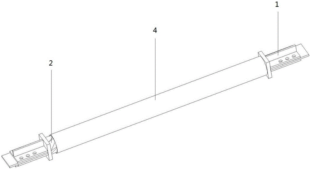
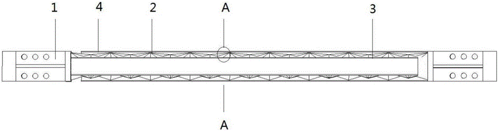
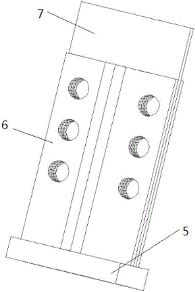
[0030] Such as figure 1 , 2 As shown, it is composed of an end restraint section 1, a buckling induction section 2, an inner sleeve 3 and an outer sleeve 4. The end restraint section 1 is fixed at both ends of the buckling induction section 2. The left end of the inner sleeve is welded to the square steel plate 5 of the left end restraint section 1, and the right end of the inner sleeve is at a distance from the square steel plate of the right end restraint section, and the distance is not less than 1 / 40 of the length of the buckling induction section ; The right end of the outer sleeve is welded to the square steel plate 5 of the right end restraint section 1, and the left end of the outer sleeve is a distance from the square steel plate of the left end restraint section, and the distance is not less than 1 / 40 of the length of the buckling induction section . Such as Figure 5~7 A...


PUM


Abstract

The invention discloses a casing pipe flexion induction supporting with a bidirectional spiral induction unit. The casing pipe flexion induction support is formed by end part restraint sections, a flexion induction section, an internal casing pipe and an external casing pipe, wherein the flexion induction section is clamped between the internal casing pipe and the external casing pipe; the internal and external casing pipes are respectively connected with one end restraint section; the flexion induction section is formed by at least one bidirectional spiral induction unit along a supporting axis direction; the bidirectional spiral induction unit is a spatial body with a cross section being in a regular-m polygonal shape and the spatial body formed by m bidirectional spiral sub-units annularly arrayed to form; and bidirectional spiral sub-unit is a spatial body formed by four triangular plates folded and with each two sharing the same line. The casing pipe flexion induction supporting can maintain elasticity with an action of slight vibration; upon medium or big vibration, the flexion induction section enters a flexion phase, and a damper effect can be achieved due to great hysteretic energy performance; and the casing pipe flexion induction supporting can be prefabricated in factories, so on-site construction load can be reduced and the casing pipe flexion induction supporting is energy-saving and environment-protective.

Description

Technical field [0001] The invention belongs to the technical field of building structures, and particularly relates to a casing buckling induction support with a bidirectional spiral induction unit, which is suitable for steel structures or concrete structures with buckling restraint supports. Background technique [0002] During the use of steel structures or reinforced concrete structures, ordinary supports will buckle under compression. When the supports buckle under compression, their stiffness and bearing capacity will drop sharply. Under the action of earthquake or wind, the internal force of the support changes back and forth under both compression and tension. When the support gradually changes from the buckled state to the tensioned state, the internal force and stiffness of the support are close to zero. Therefore, the hysteretic performance of ordinary supports is poor under repeated loads. In order to solve the problem of common support’s compression buckling and p...

Claims


Application Information

Patent Timeline
Patent Type & Authority Applications(China)
IPC IPC(8): E04H9/02E04B1/98
CPCE04H9/021
Inventor 蔡建国冯健刘鹏周宇航柳杨青
Owner SOUTHEAST UNIV
Why Eureka
Try Eureka