Test bench used for measuring radial bearing work clearance and method thereof

A technology of test bench and clearance, applied in the direction of measuring device, mechanical measuring device, electrical device, etc., can solve the problems of poor loading force, low data accuracy, and inability to measure working clearance, etc., to achieve high precision and test Accurate, reasonable and reliable experimental equipment

Active Publication Date: 2017-03-08
DALIAN UNIV OF TECH
7 Cites 17 Cited by

AI-Extracted Technical Summary

Problems solved by technology

There are problems such as poor control of loading force, low data accuracy, ...

Abstract

The invention provides a test bench used for measuring a radial bearing work clearance and a method thereof. One end of a shaft coupling of the test bench is connected to a left end of a rotating shaft, and the other end is connected to a driving motor. A fulcrum 1 and a fulcrum 2 are used for supporting the rotating shaft to rotate. A detected fulcrum is placed in a central section of the rotating shaft and is fixed to an intermediate support seat. The intermediate support seat is located at a middle position of a left support seat and a right support seat. A hydraulic cylinder is installed on an upper surface of the intermediate support seat and is placed right below the detected fulcrum. Through hydraulic loading, radial loading to the detected fulcrum is realized. Three eddy current sensors are used for measuring and representing an inner and outer ring vertical radial displacement of a roller bearing, and calculating a radial work clearance of the roller bearing. The test bench is used for realizing vertical radial work clearance measurement of the roller bearing. The test bench and the method have advantages that a radial work clearance during a bearing rotation process can be measured; measurement is accurate and reliable; an experiment apparatus can realize the radial bearing work clearance measurement; and real-time dynamic monitoring is achieved and precision is high.

Application Domain

Using electrical meansMechanical measuring arrangements

Technology Topic

Time dynamicsDrive motor +10

Image

  • Test bench used for measuring radial bearing work clearance and method thereof
  • Test bench used for measuring radial bearing work clearance and method thereof
  • Test bench used for measuring radial bearing work clearance and method thereof

Examples

  • Experimental program(1)

Example Embodiment

[0027] The present invention will be further described below with reference to the drawings and embodiments.
[0028] The measurement method is based on the relative displacement of the inner and outer rings of the bearing.
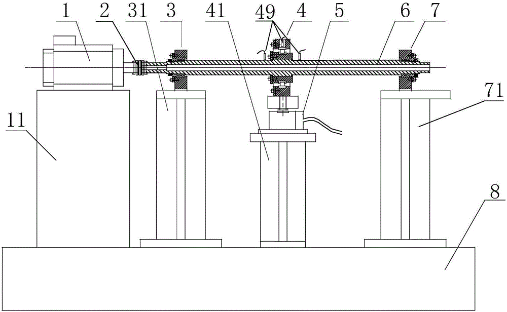
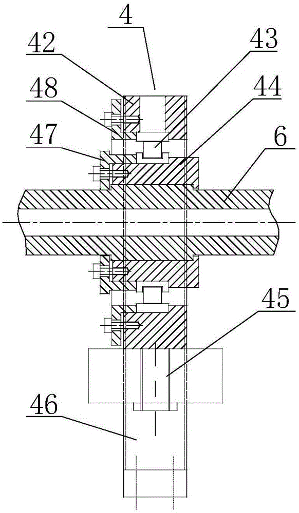
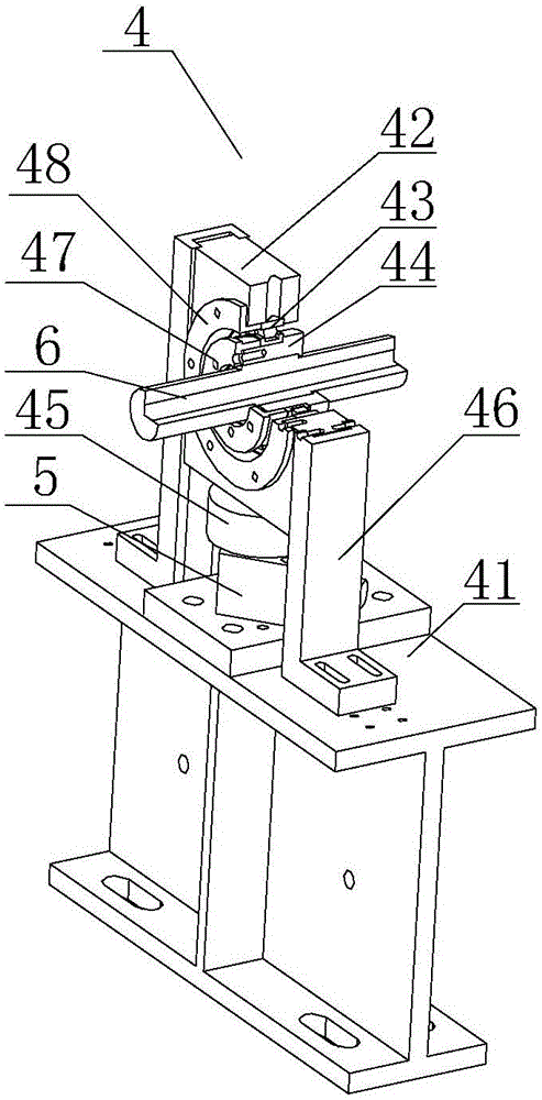
[0029] Combine figure 1 , A test bench for measuring radial working clearance of bearings, including drive motor 1, motor base 11, coupling 2, fulcrum one 3, left support 31, tested fulcrum 4, eddy current sensor 49, middle support 41. Hydraulic cylinder 5, rotating shaft 6, fulcrum two 7, right support 71 and bottom platform 8.
[0030] The coupling 2 is an elastic coupling or a rigid coupling, one end of which is connected to the rotating shaft 6 to drive the rotating shaft 6 to rotate, and the other end is connected to the driving motor 1; the driving motor 1 is connected to the motor base 11 through bolts The upper surface of the fulcrum 3 and the fulcrum 2 are fixedly connected; the fulcrum 1 3 and the fulcrum 2 7 adopt a double deep groove ball bearing surface-mounted structure to support the rotation of the shaft 6; The bearing 36 is connected to the shaft 6 and connected to the left support 31 by bolts; the fulcrum 7 is located on the right side of the test bench, and is connected to the shaft 6 by a deep groove ball bearing, and is connected to the right support 71 by bolts; The hydraulic cylinder 5 is installed on the upper surface of the intermediate support 41 by bolts, and the radial load on the roller bearing 43 in the tested fulcrum 4 is realized by hydraulic loading; the eddy current sensor 49 is used to measure the roller bearing 43 The radial displacement of the inner and outer rings is calculated, and the radial working clearance of the roller bearing 43 is calculated; the left support 31, the middle support 41, and the right support 71 are connected to the bottom platform 8 by bolts to support the experimental rotor system.
[0031] Combine figure 2 and image 3 The tested fulcrum 4 includes a positioning bearing seat 42, a roller bearing 43, a shaft sleeve 44, a pressure sensor 45, a vertical rail 46, an inner ring gland 47, and an outer ring gland 48. The shaft 6 has a raised step in the middle; the inner and outer rings on the right side of the sleeve 44 have raised ribs; the inner ring of the sleeve 44 has an interference fit with the step surface on the right side of the shaft 6; The inner ring of the roller bearing 43 is fixedly matched with the outer ring and rib of the sleeve 44; the inner ring gland 47 is fixedly matched with the left end surface of the sleeve 44 by bolts, and is used to fix the inner ring of the roller bearing 43 Axial position; the outer ring gland 48 is fixedly matched with the left end surface of the positioning bearing seat 42 by bolts, and is used to fix the axial position of the outer ring of the roller bearing 43;
[0032] The pressure sensor 45 is fixedly connected to the bottom of the positioning bearing seat 42 by bolts; the hydraulic cylinder 5 is fixedly connected to the upper surface of the intermediate support 41 by bolts, and is placed directly below the pressure sensor 45. By supplying oil to the hydraulic cylinder 5, the upper surface of the hydraulic cylinder 5 is in contact with the pressure sensor 45, and the positioning bearing seat 42 is displaced upward, and the generated load drives the roller bearing 43 to move radially.
[0033] Combine image 3 4, the upper surface of the intermediate support 41 is fixedly connected to the bottom of the vertical rail 46 by bolts to determine the position of the vertical rail 46, and the lower surface of the intermediate support 41 is fixedly connected to the base 8 by bolts; The positioning bearing seat 42 includes a mounting hole 421 and mounting side surfaces 422, 423; the mounting hole 421 is used to mount the discharge eddy current sensor 49; the vertical rail 46 includes guide rail positioning surfaces 461, 462; the vertical rail 46 The positioning surface 461 of the guide rail is matched with the mounting side surface 423, and the positioning surface 462 and the mounting side surface 422 are used to determine the position of the bearing seat 42 and further determine the position of the tested fulcrum 4;
[0034] Combine Figure 5 The fulcrum one 3 includes a bearing seat 32, a bearing seat gland 33, a ferrule 34, a lock nut 35, and a pair of deep groove ball bearings 36; the fulcrum two 7 has the same structure and principle as the fulcrum one 3.
[0035] The inner ring of the deep groove ball bearing 36 is fixed on the shaft 6; the bearing seat cover 33 and the shaft shoulder of the shaft 6 are used to axially fix the outer ring of the deep groove ball bearing 36; the lock nut 35 It is used to lock the inner ring of the deep groove ball bearing 36; the bearing seat 32 is fixedly installed on the upper surface of the left support 31; the bottom of the left support 31 is fixedly connected to the base 8 by bolts.
[0036] Combine Image 6 The measurement and control system includes a sensor, a data acquisition instrument, a signal acquisition controller and a PC terminal. The sensors include pressure sensors and eddy current sensors. The pressure sensor and the eddy current sensor are directly connected to the data acquisition instrument. After the signal acquisition controller and PC terminal processing, the radial load value applied by the hydraulic cylinder and the vertical radial displacement of the inner and outer rings of the roller bearing are measured in real time.
[0037] Combine Figure 7 The eddy current sensor 49 is vertically mounted on the left shaft end of the positioning bearing seat 42, the mounting hole 421 of the positioning bearing seat 42, and the right shaft end of the positioning bearing seat 42 through the magnetic support. The roller bearing rotates at a speed of ω, and the force F generated by the hydraulic cylinder is transmitted to the positioning bearing seat through the pressure sensor to realize radial loading. Three eddy current sensors are used to measure the vertical radial displacement of the inner and outer rings of the roller bearing. The middle sensor directly measures the vertical radial displacement of the outer ring of the roller bearing. o , The left and right sensors characterize the vertical radial displacement of the inner ring by measuring the average value of the shaft displacement i , The vertical radial displacement value of the bearing outer ring relative to the inner ring Δy = y o -y i , Which is the radial working clearance of the bearing.

PUM

no PUM

Description & Claims & Application Information

We can also present the details of the Description, Claims and Application information to help users get a comprehensive understanding of the technical details of the patent, such as background art, summary of invention, brief description of drawings, description of embodiments, and other original content. On the other hand, users can also determine the specific scope of protection of the technology through the list of claims; as well as understand the changes in the life cycle of the technology with the presentation of the patent timeline. Login to view more.

Similar technology patents

Automobile rain test bench

PendingCN113624510Atest accurate
Owner:湖北欧阳华俊专用汽车有限公司

Novel component test fixture

InactiveCN109507455Atest accurateWide versatility
Owner:四川九洲空管科技有限责任公司

High abrasion-resistant alloy cast iron drying cylinder for papermaking machinery

InactiveCN101629395Atest accurateHigh movement precision
Owner:JIANGSU HUADONG PAPER MACHINERY

Classification and recommendation of technical efficacy words

  • test accurate

Device and method for testing remote controller

InactiveCN101201377Atest accurate
Owner:SHENZHEN SKYWORTH RGB ELECTRONICS CO LTD

Biaxial cruciform tensile testing device

ActiveCN106908319Atest accurate
Owner:SHANDONG UNIV

Pneumatic material impact test device simulating shooting of bullet (cannonball)

InactiveCN104089833Atest accuratelarge range
Owner:NANCHANG HANGKONG UNIVERSITY

Synchronization testing device and testing method of thermal barrier performance and thermal shock performance of thermal barrier coating

InactiveCN103134828Atest accurateEffective evaluation of spraying effect
Owner:ADVANCED MFG TECH CENT CHINA ACAD OF MASCH SCI & TECH +1

Face detection algorithm test method and device

ActiveCN106327546Atest accurate
Owner:BEIJING KUANGSHI TECH +1
Why Eureka
Try Eureka