
Ultrasonic wind finding system and method

An ultrasonic and wind speed technology, which is applied in measuring devices, fluid speed measurement, speed/acceleration/shock measurement, etc., can solve the problems of large measurement errors and affecting the measurement performance of the wind measurement system, shorten the distance, improve the anti-interference ability and The effect of stability and reliability

Active Publication Date: 2017-03-08
STATE OCEAN TECH CENT
View PDF8 Cites 14 Cited by
  • Summary
  • Abstract
  • Description
  • Claims
  • Application Information

AI Technical Summary

Problems solved by technology

At present, the measurement method used by the ultrasonic wind measurement system of automatic weather stations is mostly the time difference method. The ultrasonic wind measurement system based on the time difference measurement method has certain requirements for the distance between the ultrasonic transducers that send and receive ultrasonic signals. The smaller the distance , the shorter the time interval between driving the ultrasonic transducer to transmit the ultrasonic signal and receiving the ultrasonic echo signal, the greater the measurement error, which directly affects the measurement performance of the entire wind measurement system
In order to ensure the measurement accuracy and stability of the overall wind measurement system, the relatively mature ultrasonic wind measurement system on the market currently uses the time difference measurement method, and the sound path is basically above 100mm. It is difficult to realize the miniaturization of the wind measurement system

Method used


Image

  • Ultrasonic wind finding system and method
  • Ultrasonic wind finding system and method
  • Ultrasonic wind finding system and method

Examples


Embodiment Construction

[0041] The following will clearly and completely describe the technical solutions in the embodiments of the present invention with reference to the accompanying drawings in the embodiments of the present invention. Obviously, the described embodiments are only some, not all, embodiments of the present invention. Based on the embodiments of the present invention, all other embodiments obtained by persons of ordinary skill in the art without making creative efforts belong to the protection scope of the present invention.

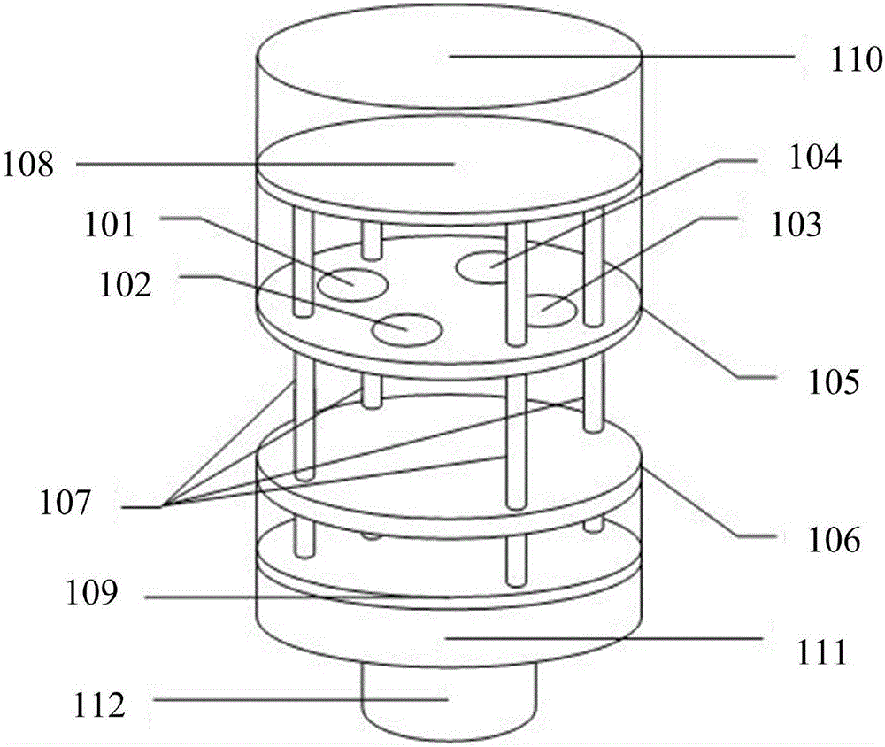
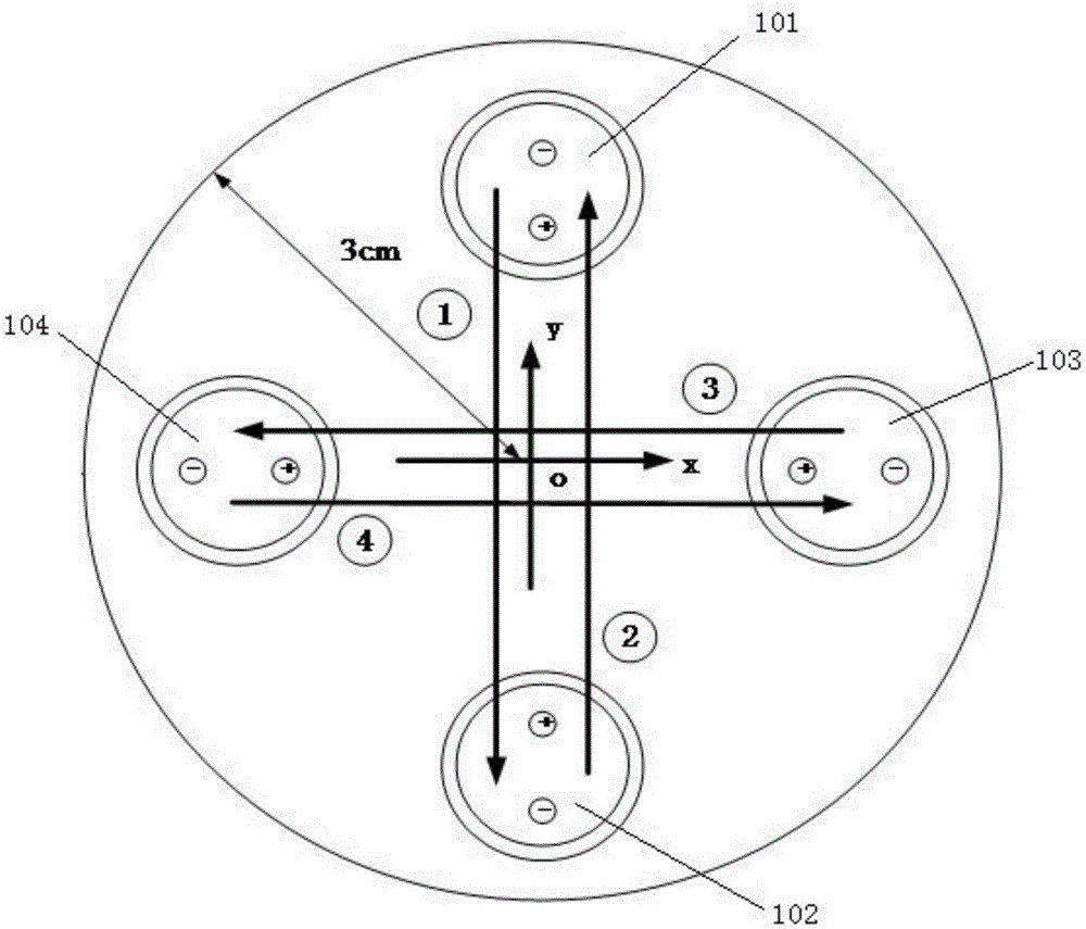
[0042] The purpose of the present invention is to provide an ultrasonic wind measurement system and method capable of realizing the miniaturization of the wind measurement system while ensuring the accuracy of the measurement results.

[0043] In order to make the above objects, features and advantages of the present invention more comprehensible, the present invention will be further described in detail below in conjunction with the accompanying drawings and s...


PUM


Abstract

The invention discloses an ultrasonic wind finding system and method. The system is composed of ultrasonic transducer probes, a circuit board, a pedestal, and a reflection plane. The ultrasonic transducer probes are used for transmitting and receiving pulse signals having set lobe widths; each two ultrasonic transducer probes are opposite to each other and form one group; a connecting line between each two ultrasonic transducer probes opposite to each other is marked as a connecting wire; and at least two groups of connecting wires in the system are perpendicular to each other. An ultrasonic wave emitted by the ultrasonic transducer probe in each group is reflected by the reflection plane and then can be received by the other ultrasonic transducer probe in the same group as the ultrasonic transducer probe and only can be received by the other ultrasonic transducer probe in the same group as the ultrasonic transducer probe. Using the method and system provided by the invention, accuracy of a measuring result is guaranteed and miniaturization of the wind finding system is realized.

Description

technical field [0001] The invention relates to the field of wind speed measurement, in particular to an ultrasonic wind measurement system and method. Background technique [0002] In order to meet the development needs of my country's ocean observation, it is urgent to develop a small integrated automatic weather station. At present, the measurement method used by the ultrasonic wind measurement system of automatic weather stations is mostly the time difference method. The ultrasonic wind measurement system based on the time difference measurement method has certain requirements for the distance between the ultrasonic transducers that send and receive ultrasonic signals. The smaller the distance , the shorter the time interval between driving the ultrasonic transducer to transmit the ultrasonic signal and receiving the ultrasonic echo signal, the greater the measurement error, which directly affects the measurement performance of the entire wind measurement system. In ord...

Claims


Application Information

Patent Timeline
IPC IPC(8): G01P5/24G01P13/02
CPCG01P5/244G01P13/02Y02A90/10
Inventor 孔佑迪张鹏王海涛王斌孙东波赵辰冰党超群顾季源王心鹏门雅彬刘宁李永军张锁平
Owner STATE OCEAN TECH CENT
Features
  • Generate Ideas
  • Intellectual Property
  • Life Sciences
  • Materials
  • Tech Scout
  • Unparalleled Data Quality
  • Higher Quality Content
  • 60% Fewer Hallucinations
Learn More