
Spiral elevating ground wire drill device

A technology of spiral lifting and ground wire brazing, which is applied in the direction of cable installation devices, cable installation, electrical components, etc., can solve the problems of difficult extraction of ground wire brazing, inconvenient handling of the device, and large height of the device, and achieves easy extraction and simple structure , the effect of easy operation

Inactive Publication Date: 2017-03-08
国网山东省电力公司曹县供电公司
View PDF8 Cites 0 Cited by
  • Summary
  • Abstract
  • Description
  • Claims
  • Application Information

AI Technical Summary

Problems solved by technology

Temporary grounding of wires is generally to connect the wires with the ground wire nailed into the ground. The ground wire generally consists of a drill cap and a straight rod set under the drill cap. To ensure reliable grounding, the straight rod part of the ground wire needs to be It is nailed to a deep position below the ground, because the straight rod of the ground wire is nailed deeply, which makes it very difficult to pull out the ground wire
[0003] The Chinese patent with the notification number CN 102447231B discloses a ground wire brazing puller, although the puller can successfully pull out the ground wire brazing, but during the pulling process, since the ground wire brazing is located on the side of the whole device , so that the shell is subjected to a large moment, it is easy to cause the whole device to be skewed to the position of the ground wire, and at the same time, due to the long ground wire, the height of the entire device is also large, making the device inconvenient to carry

Method used


Image

  • Spiral elevating ground wire drill device
  • Spiral elevating ground wire drill device
  • Spiral elevating ground wire drill device

Examples


Embodiment Construction

[0020] Below will combine specific embodiment and appended Figure 1-5 , clearly and completely describe the technical solutions in the embodiments of the present invention, obviously, the described embodiments are only some preferred embodiments of the present invention, not all the embodiments. Those skilled in the art can make similar modifications without departing from the connotation of the present invention, so the present invention is not limited by the specific embodiments disclosed below.

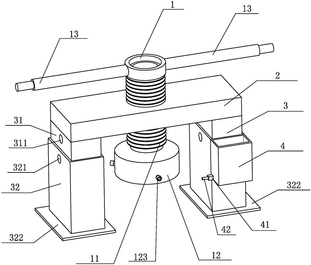
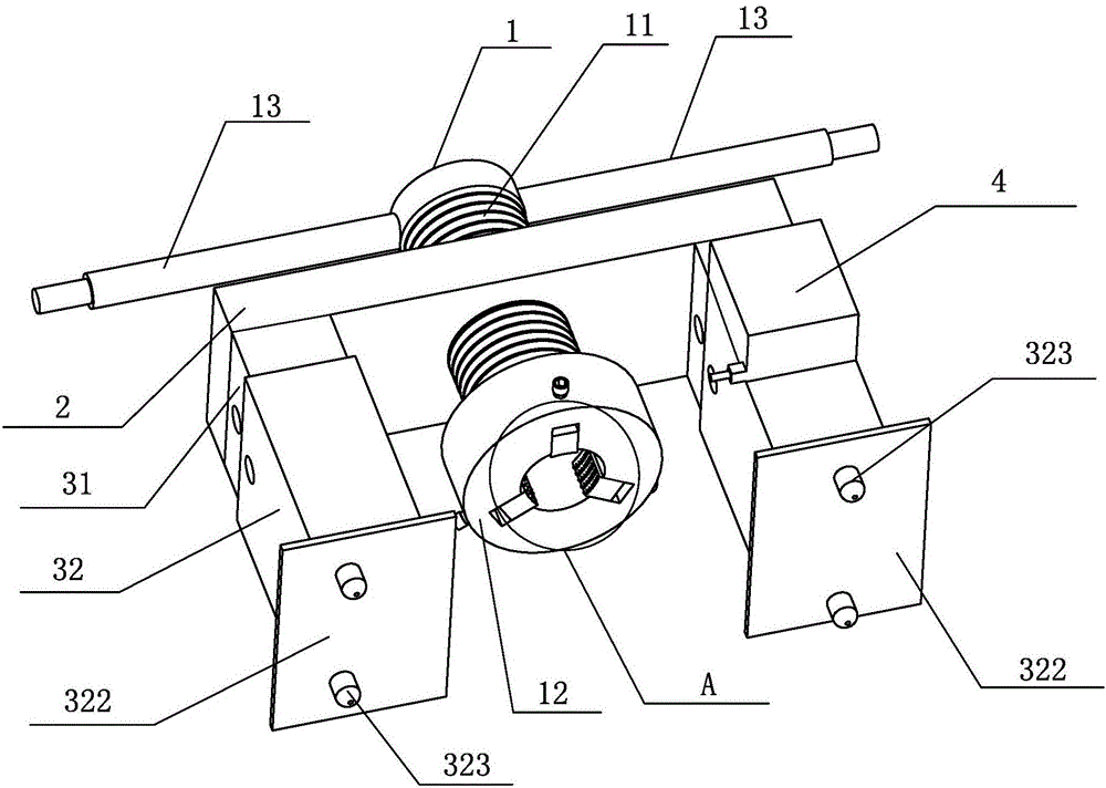
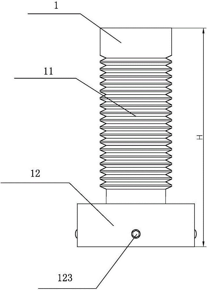
[0021] The invention provides a kind of spiral lifting ground wire brazing device (such as figure 1 shown), including a horizontal plate 2, a hollow tube 1 and a clamping device, an external thread 11 is arranged on the outer peripheral side wall of the hollow tube 1, and an external thread 11 is arranged in the middle of the horizontal plate 2 Cooperating threaded through holes, a pair of supporting legs 3 are symmetrically arranged at both ends of the lower bottom surface of th...


PUM


Abstract

The invention provides a spiral elevating ground wire drill device, which comprises a transverse plate, a hollow circular pipe, a clamping device and a water storage tank, wherein an external thread is arranged in the outer circumferential side wall of the hollow circular pipe; a threaded through hole matched with the external thread is arranged in the middle part of the transverse plate; a pair of support legs is symmetrically arranged at two ends of the lower bottom surface of the transverse plate; a pair of thrust levers is symmetrically arranged at the upper end of the hollow circular pipe; and the water storage tank is arranged at the outer side of one support leg. When a ground wire drill is extracted by using the device, the ground wire drill is located at the center position of the whole device, so that the phenomenon of deflection of the whole device in the extraction process is avoided. Meanwhile, the ground wire drill is extracted by the device in a manner of elevating while rotating, so that the friction force of the ground wire drill in the vertical direction is effectively decomposed in the rotating process, the ground wire drill is more easily extracted and the extraction working strength is further reduced.

Description

technical field [0001] The invention relates to an auxiliary tool for electric power construction operations, in particular to a spiral lifting ground wire brazing device. Background technique [0002] At the electric power construction site, in order to ensure the safety of electric power construction, it is necessary to temporarily ground the wires that may be touched during the construction process. Temporary grounding of wires is generally to connect the wires with the ground wire nailed into the ground. The ground wire generally consists of a drill cap and a straight rod set under the drill cap. To ensure reliable grounding, the straight rod part of the ground wire needs to be It is nailed into a deep position below the ground, because the straight rod part of the ground wire is nailed deeply, which makes it very difficult to pull out the ground wire. [0003] The Chinese patent with the notification number CN 102447231B discloses a ground wire brazing puller, although...

Claims


Application Information

Patent Timeline
IPC IPC(8): H02G1/00
CPCH02G1/00
Inventor 罗严涛祝天玉杨博曹光宇王志华葛晓东王冬梅
Owner 国网山东省电力公司曹县供电公司
Learn More