
Permanent magnet synchronous motor state estimation method based on sliding mode back EMF observer

A technology of permanent magnet synchronous motor and back electromotive force, which is applied in the direction of motor generator control, electromechanical brake control, electronic commutation motor control, etc. It can solve problems such as rotor position phase lag, suppress chattering, and improve dynamic tracking performance and the effect of estimating the accuracy of

Inactive Publication Date: 2017-03-08
JIANGSU UNIV
View PDF5 Cites 27 Cited by
  • Summary
  • Abstract
  • Description
  • Claims
  • Application Information

AI Technical Summary

Problems solved by technology

Back-EMF chattering estimated in traditional sliding mode observers is severe, and the solution is usually to filter with a low-pass filter, which causes a phase lag in the estimated rotor position

Method used


Image

  • Permanent magnet synchronous motor state estimation method based on sliding mode back EMF observer
  • Permanent magnet synchronous motor state estimation method based on sliding mode back EMF observer
  • Permanent magnet synchronous motor state estimation method based on sliding mode back EMF observer

Examples


Embodiment Construction

[0030] The present invention will be further described below in conjunction with the accompanying drawings.

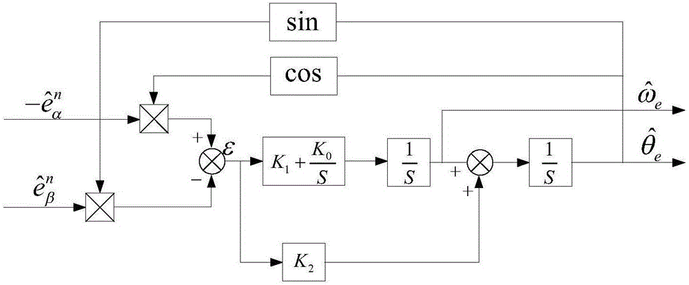
[0031] figure 1 with figure 2 Be respectively the block diagram of the principle of the sliding mode back EMF observer of the present invention and the block diagram of the phase-locked loop type position observer of the PI-I structure, and the specific implementation steps are:

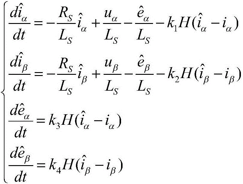
[0032] Step (1): Construct a sliding mode back EMF observer, the back EMF estimated by this observer is

[0033] In the two-phase stationary coordinate system, the stator current state equation can be expressed as:

[0034]

[0035] Among them, the back electromotive force of the permanent magnet synchronous motor is:

[0036]

[0037] Among them, i a i β Respectively, the components of the stator current on the a and β axes in the two-phase stationary coordinate system, u a , u β Respectively, the components of the stator voltage on the a and β axes in the two-phase stationar...


PUM


Abstract

The invention discloses a permanent magnet synchronous motor state estimation method based on a sliding mode back EMF observer. According to stator voltage and stator current detected in real time, a sigmoid function is used to substitute a sign function, and the sliding mode back EMF observer is constructed to estimate the back EMF. The type of the sliding mode back EMF observer is characterized in that the observer is insensitive to switch noise and has a filtering characteristic, thus the filtering of the estimated back EMF through a low-pass filter is not needed. After the normalization processing of the back EMF, a rotor position and speed information are extracted through a PI-I structure phase-locked loop position observer equivalent to a simplified Kalman filter. The permanent magnet synchronous motor state estimation method of the invention has good estimation performance even in the condition of noise and motor parameter changes, the chattering phenomenon in a traditional sliding mode observer is reduced, and the dynamic tracking performance and estimation precision of the rotor position and speed are improved.

Description

technical field [0001] The invention relates to the field of sensorless control of permanent magnet synchronous motors, in particular to a state estimation method of permanent magnet synchronous motors. Background technique [0002] In recent decades, permanent magnet synchronous motors have been widely used in high-performance servo systems due to their small size, high efficiency, high power density, and good dynamic performance. Accurate position and velocity information is critical for vector control of permanent magnet synchronous motors. The position and speed of the rotor can be detected by installing mechanical sensors such as photoelectric encoders on the rotor shaft, but these sensors not only increase the cost but also reduce the reliability of the system, while limiting the application range of permanent magnet synchronous motors. Therefore, researching the sensorless technology of permanent magnet synchronous motor has important theoretical and practical value....

Claims


Application Information

Patent Timeline
IPC IPC(8): H02P21/24H02P21/28
CPCH02P21/0007
Inventor 许波沐方强姬伟时国定丁世宏
Owner JIANGSU UNIV
Learn More