Cardiac pacemaker device

A cardiac pacemaker and cardiac pacing technology, applied in cardiac stimulators, electrotherapy, treatment, etc., can solve problems that are easily affected and have not been widely used, so as to achieve safe use, reduce surgical risks, and improve use safety effect

Inactive Publication Date: 2017-03-15
邝继伍
View PDF0 Cites 4 Cited by
  • Summary
  • Abstract
  • Description
  • Claims
  • Application Information

AI Technical Summary

Problems solved by technology

[0003] At present, there are also wireless charging for cardiac pacemakers through wireless chargers, and wireless charging equipment is directly added to cardiac pacemakers. Since wireless charging equipment uses magnetoelectric conversion technology to c

Method used


Image

  • Cardiac pacemaker device
  • Cardiac pacemaker device
  • Cardiac pacemaker device

Examples


Embodiment 1

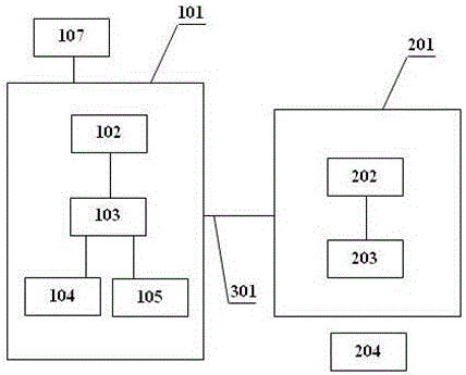
[0037] Such as figure 1 As shown, the present invention separates the cardiac pacemaker 101 from the wireless charging receiver 203, the communication between the cardiac pacemaker 101 and the external detection equipment is transferred to the auxiliary power supply device 201, and the cardiac pacemaker 101 can adopt a fully enclosed metal casing It can better shield the electromagnetic interference from the outside, making the use of the pacemaker 101 safer and more reliable.

[0038] 1. The wireless charger 204 outside the body transmits power to the wireless charging receiver 203 on the auxiliary power supply device 201, and the wireless charging receiver 203 controls the received power through the control system B202 and transmits it to the cardiac pacemaker through the connecting wire 301 101, which is then stored by the battery 104 provided in the cardiac pacemaker 101; through the control system A103, the power supply to the cardiac pacemaker 102 in the cardiac pacemake...

Embodiment 2

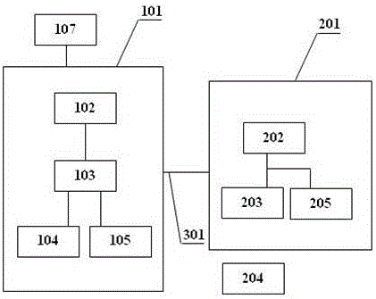
[0041] Such as figure 2 As shown, on the basis of Embodiment 1, an electric storage device 205 is added.

[0042] 1. The wireless charger 204 transmits electric energy to the wireless charging receiver 203. The electric energy received by the wireless charging receiver 203 is sent to the power storage device 205 for storage. Another routing control system B202 controls the electric energy to be sent to The battery 104 in the pacemaker 101.

[0043] 2. Both the storage device 205 and the storage battery 104 can supply power to the pacemaker 101 at the same time, and the storage device 205 acts as a backup power supply, making the power supply of the pacemaker device more secure.

Embodiment 3

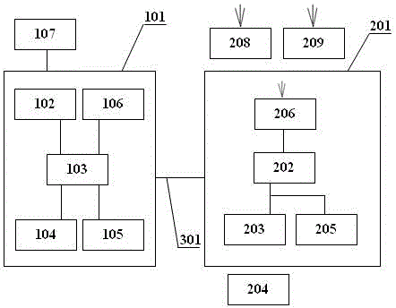
[0045] Such as image 3 As shown, on the basis of the second embodiment, the cardiac pacemaker 101 is provided with a memory 106 , and the auxiliary power supply device 201 is provided with a remote wireless communication device 206 and a medical monitor 209 .

[0046] 1. The wireless charger 204 transmits electric energy to the wireless charging receiver 203, and the wireless charging receiver 203 stores the electric energy from the power storage device 205, and at the same time, it is controlled by the control system B202 and transmitted to the cardiac pacemaker 101 through the connecting wire 301 In the accumulator 104 inside; the accumulator device 205 and the accumulator 104 provided can supply power to the cardiac pacemaker 101, and play the role of a backup power supply, making the power supply of the present invention more secure.

[0047] 2. When the internal detector 105 detects that the cardiac pacemaker 101 is working normally, the control system A103 stores the da...


PUM


Abstract

The invention discloses a cardiac pacemaker device, including a cardiac pacemaker and an auxiliary power supply device, the two parts are connected through a connecting wire to intercommunicate to work, and technologies of wireless charging, wireless intelligent communication, environment sensing, electromagnetic shielding and the like are utilized at the same time; the situation that since the electric quantity of a cardiac pacemaker is used up, a battery needs to be replaced can be avoided, and adverse effects of a relatively high magnetic field environment on a patient carrying the cardiac pacemaker are avoided; and use of the cardiac pacemaker device is relatively safe, the device contributes to collection and monitoring of patient condition clinical medical data by medical staff and monitoring of the physical condition of a patient by the patient himself or guardian thereof, and a positive prevention effect is achieved.

Description

technical field [0001] The invention relates to the technical field of cardiac pacemakers, in particular to a cardiac pacemaker device. Background technique [0002] At present, the general service life of cardiac pacemakers is about 5--8 years. When the service life comes, the battery power inside the cardiac pacemaker is often exhausted, and the battery of the cardiac pacemaker needs to be replaced again. The patient brings greater surgical risk and pain. [0003] At present, there are also wireless charging for cardiac pacemakers through wireless chargers, and wireless charging equipment is directly added to cardiac pacemakers. Since wireless charging equipment uses magnetoelectric conversion technology to charge cardiac pacemakers, the current cardiac pacemaker The device incorporates more wireless communication monitoring methods, and there are large uncertainties in the electromagnetic field, which is easy to cause influence, so it has not been widely used. [0004] ...

Claims


Application Information

Patent Timeline
IPC IPC(8): A61N1/375A61N1/378A61N1/362A61N1/372A61N1/37
CPCA61N1/375A61N1/362A61N1/3718A61N1/37217A61N1/378A61N1/3787
Inventor 邝继伍
Owner 邝继伍
Why Eureka
Try Eureka