Gluing and pressing device for automobile lamps

A pressing device and a technology for automobile lamps, which are applied to the surface coating liquid device, material gluing, coating, etc., can solve the problems of increasing the workload of the staff, spending a lot of time on rework, and low production efficiency. The structure is simple, the degree of automation is high, and the effect of improving production efficiency

Inactive Publication Date: 2017-03-15
DANYANG ZHENGLIAN INTPROP OPERATIONS MANAGEMENT CO LTD
View PDF9 Cites 7 Cited by
  • Summary
  • Abstract
  • Description
  • Claims
  • Application Information

AI Technical Summary

Problems solved by technology

[0002] The production process of car lights involves the step of gluing and pressing. Specifically, glue is applied to the upper end of the car lamp and then the lampshade is pressed on the car lamp. Most of the existing enterprises use manual gluing, and then press the lampshade on the lampshade. , increase the workload of the staff, and at the same time, the production efficiency is not high. Some enterprises need to manually align the headlights with the gluing device for mobile gluing during the gluing process. Because the speed of manual movement is difficult to control, the gluing part will Uniform, and at the same time glue is harmful to the human body. Some companies have misplaced the pressed cover due to the inaccurate placement of the lamp cover during pressing, and it takes a lot of time to rework

Method used


Image

  • Gluing and pressing device for automobile lamps
  • Gluing and pressing device for automobile lamps
  • Gluing and pressing device for automobile lamps

Examples


Embodiment Construction

[0016] In order to enhance the understanding of the present invention, the present invention will be further described in detail below in conjunction with the accompanying drawings and embodiments, which are only used to explain the present invention and do not limit the protection scope of the present invention.

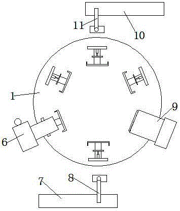
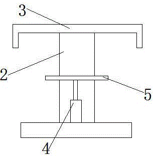
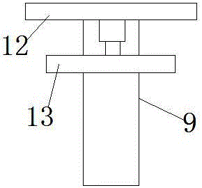
[0017] Such as Figure 1-2 As shown, the present invention is a kind of glue coating and laminating device for automobile lights, comprising a rotary table 1, on which several fixing devices for fixing the lights are arranged, and the fixing devices include a fixing base 2, on which the fixing base 2 The front side of the upper end is provided with a front side baffle plate 3, a rear side fixed plate is provided at the rear side of the fixed seat 2 upper end, an automatic push rod 4 is provided on the rear side fixed plate, and an automatic push rod (4) front end is provided with The movable baffle 5 is provided with a gluing device 6 on the right side of the rotary...


PUM


Abstract

The invention discloses a gluing and pressing device for automobile lamps. The gluing and pressing device comprises a rotating workbench. A plurality of fixing devices are arranged on the rotating workbench. Each fixing device comprises a fixing base. A front side baffle is arranged on the front side of the upper end of each fixing base, and a rear side fixing plate is arranged on the rear side of the upper end of each fixing base. Each rear side fixing plate is provided with an automatic push rod. The front end of each automatic push rod is provided with a movable baffle. A gluing device is arranged at the right side of the rotating workbench. A feeding conveyor belt is arranged on the rear side of the rotating workbench, and a feeding mechanical arm is arranged between the feeding conveyor belt and the rotating workbench. A pressing device is arranged on the side edge of the rotating workbench and located on the rear side of the feeding mechanical arm. A discharging conveyor belt is arranged on the side edge of the rotating workbench and located on the rear side of the pressing device, and a discharging mechanical arm is arranged between the discharging conveyor belt and the rotating workbench. The gluing and pressing device is simple in structure and reasonable in design, gluing evenness can be guaranteed, the pressing position is accurate, the degree of automation is high, labor intensity of workers is effectively relieved, and production efficiency is improved.

Description

technical field [0001] The invention relates to auto parts processing equipment, in particular to an auto lamp glue coating and pressing device. Background technique [0002] The production process of car lights involves the step of gluing and pressing. Specifically, glue is applied to the upper end of the car lamp and then the lampshade is pressed on the car lamp. Most of the existing enterprises use manual gluing, and then press the lampshade on the lampshade. , increase the workload of the staff, and at the same time, the production efficiency is not high. Some enterprises need to manually align the headlights with the gluing device for mobile gluing during the gluing process. Because the speed of manual movement is difficult to control, the gluing part will At the same time, the glue is harmful to the human body. Some companies have misplaced the pressed cover due to the inaccurate placement of the lamp cover during pressing, and it takes a lot of time to rework. Conte...

Claims


Application Information

Patent Timeline
Patent Type & Authority Applications(China)
IPC IPC(8): B23P19/027B05C13/02F16B11/00
CPCB23P19/027B05C13/02B23P19/006B23P19/007B23P2700/50F16B11/006
Inventor 张子涵
Owner DANYANG ZHENGLIAN INTPROP OPERATIONS MANAGEMENT CO LTD
Why Eureka
Try Eureka