High-maneuverability stone cutting machine

A high-mobility cutting machine technology, applied in the direction of stone processing tools, stone processing equipment, manufacturing tools, etc., can solve the problems of inability to switch flexibly, achieve the effect of improving cutting efficiency, ingenious design, and high feasibility

Active Publication Date: 2017-03-15
南通中煌工具有限公司
View PDF6 Cites 17 Cited by
  • Summary
  • Abstract
  • Description
  • Claims
  • Application Information

AI Technical Summary

Problems solved by technology

[0003] There are many deficiencies in existing stone cutting machines, one of which is exactly: most of the existing stone cutting machines have only one set of saw blades, so they need to reciprocate many times when cutting stones, and some stone cutting machines have two saw blades at the same time. Group saw blades, but when only one group is needed for cutting, it cannot be switched flexibly

Method used


Image

  • High-maneuverability stone cutting machine
  • High-maneuverability stone cutting machine
  • High-maneuverability stone cutting machine

Examples


Embodiment Construction

[0023] The present invention is described in further detail now in conjunction with accompanying drawing. These drawings are all simplified schematic diagrams, which only illustrate the basic structure of the present invention in a schematic manner, so they only show the configurations related to the present invention.

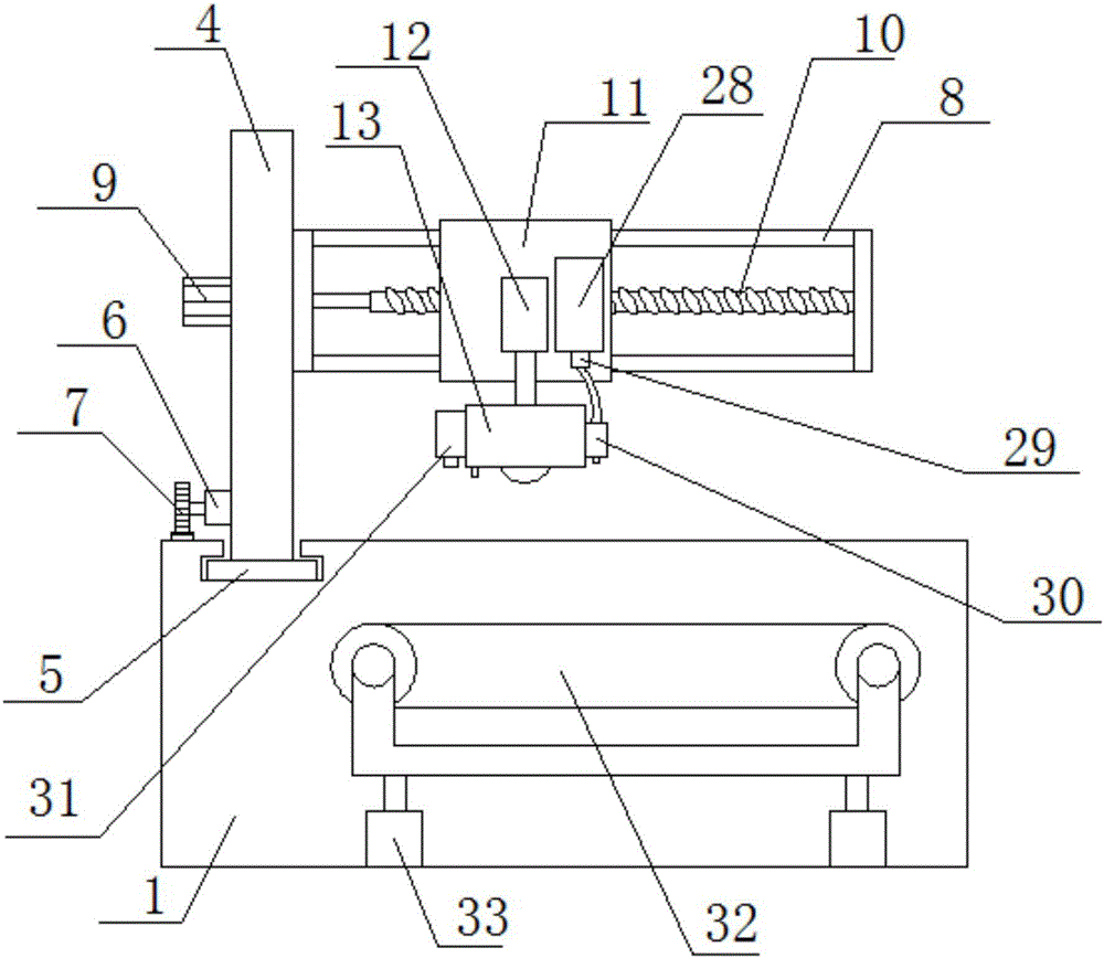
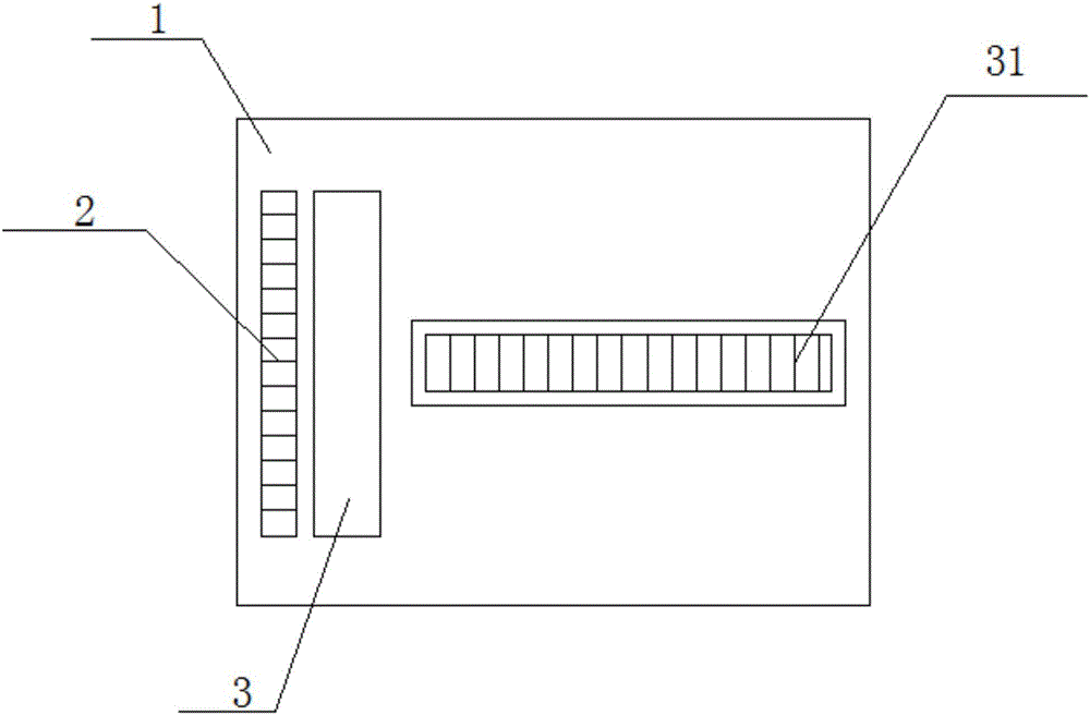
[0024] Such as Figure 1-3 As shown, a stone cutting machine with high mobility includes a base 1, a rack 2, a displacement mechanism, a traveling mechanism and a cutting mechanism;

[0025] The upper end surface of the base 1 is provided with a groove 3, the groove 3 is a T-shaped groove 3, the rack 2 is horizontally arranged on the upper end surface of the base 1, and the rack 2 is located on one side of the groove 3. side, the rack 2 is parallel to the groove 3, the displacement mechanism is arranged on the base 1, the displacement mechanism is slidably connected with the groove 3, the walking mechanism is arranged on the displacement mechanism, and the cu...


PUM


Abstract

The invention relates to a high-maneuverability stone cutting machine which comprises a base, a rack, a displacement mechanism, a travelling mechanism and a cutting mechanism. The displacement mechanism comprises a support rod, a slide block, a travelling motor and a circular gear. The travelling mechanism comprises a limit frame, a drive motor and a ball screw. The cutting mechanism comprises a support plate, a telescopic cylinder and a cutting assembly. The cutting assembly comprises a shell, a cutting motor, a first belt pulley, a second belt pulley, a first transmission shaft, a second transmission shaft, a clutch, a third belt pulley, a fourth belt pulley, a fifth belt pulley, a sixth belt pulley, a lifting motor, a connecting rod, a first saw blade and a second saw blade, wherein the cutting motor, the first belt pulley, the second belt pulley, the first transmission shaft, the second transmission shaft, the clutch, the third belt pulley, the fourth belt pulley, the fifth belt pulley, the sixth belt pulley, the lifting motor, the connecting rod, the first saw blade and the second saw blade are arranged in the shell. According to the high-maneuverability stone cutting machine, the displacement mechanism and the travelling mechanism are used in cooperation, the cutting mechanism can run at any position on the base and can conduct cutting with one saw blade when the clutch is separated and conduct cutting with the two saw blades when the clutch is united.

Description

technical field [0001] The invention relates to a stone cutting machine with high maneuverability. Background technique [0002] Stone cutting machine is also called stone cutting machine. It is a multi-knife and multi-stage stone cutting machine composed of cutting knife group, stone conveying platform, positioning guide plate and frame. It is mainly used for cutting ceramic materials such as ceramic tiles and floor tiles and stone. Simple operation and fast cutting. [0003] There are many deficiencies in existing stone cutting machines, one of which is exactly: most of the existing stone cutting machines have only one set of saw blades, so they need to reciprocate many times when cutting stones, and some stone cutting machines have two saw blades at the same time. There are two sets of saw blades, but when only one set is needed for cutting, it cannot be switched flexibly. Contents of the invention [0004] The technical problem to be solved by the present invention i...

Claims


Application Information

Patent Timeline
Patent Type & Authority Applications(China)
IPC IPC(8): B28D1/04B28D7/00B28D7/02
CPCB28D1/044B28D1/048B28D7/00B28D7/02
Inventor 吴振彪
Owner 南通中煌工具有限公司
Why Eureka
Try Eureka