A composite self-balancing bridge of an arch bridge and a suspension bridge and its construction method

A combined and self-balancing technology, which is applied in bridges, bridge construction, erection/assembly of bridges, etc., can solve the problems of material waste, structural stress, disadvantages, etc., to facilitate construction and installation, reduce structural weight, and overall structural safety high effect

Inactive Publication Date: 2018-03-16
XIAN UNIV OF SCI & TECH
View PDF6 Cites 0 Cited by
  • Summary
  • Abstract
  • Description
  • Claims
  • Application Information

AI Technical Summary

Problems solved by technology

[0004] It can be seen that the arch bridge will generate thrust on the outside, and the suspension bridge will generate tension on the outside. If the solution is solved by the structure itself (using a tie-bar arch or a self-anchored suspension bridge), there are also certain shortcomings, resulting in material waste or unfavorable structural stress.

Method used


Image

  • A composite self-balancing bridge of an arch bridge and a suspension bridge and its construction method
  • A composite self-balancing bridge of an arch bridge and a suspension bridge and its construction method
  • A composite self-balancing bridge of an arch bridge and a suspension bridge and its construction method

Examples


Embodiment 1

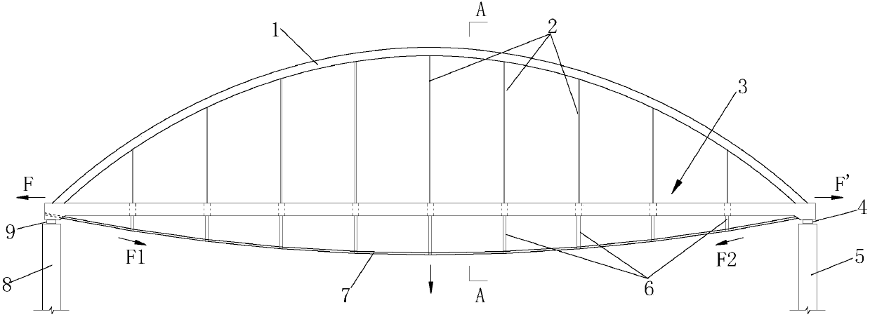
[0069] Such as figure 1 A combined self-balancing bridge of an arch bridge and a suspension bridge is shown, comprising a main girder structure 3, a bridge deck paved on the main girder structure 3, two arch rings 1 arranged above the main girder structure 3 and a Two main cables 7 below the main beam structure 3, one end of the main beam structure 3 is provided with a first bearing 4 for supporting it, and the other end of the main beam structure 3 is provided with a first support for supporting it. Two supports 9, one end of the arch ring 1 is fixed on one end of the main beam structure 3, the other end of the arch ring 1 is fixed on the other end of the main beam structure 3, and one end of the main cable 7 is fixed on the main beam One end of the structure 3, the other end of the main cable 7 is fixed on the other end of the main beam structure 3, the main beam structure 3 is connected to the arch ring 1 through the sling 2, and the main cable 7 is connected to the main be...

Embodiment 2

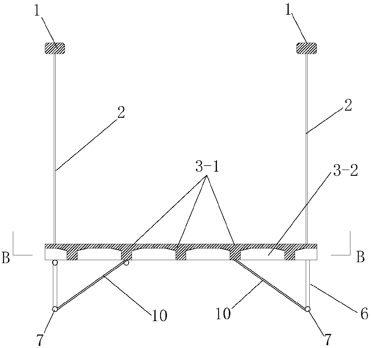
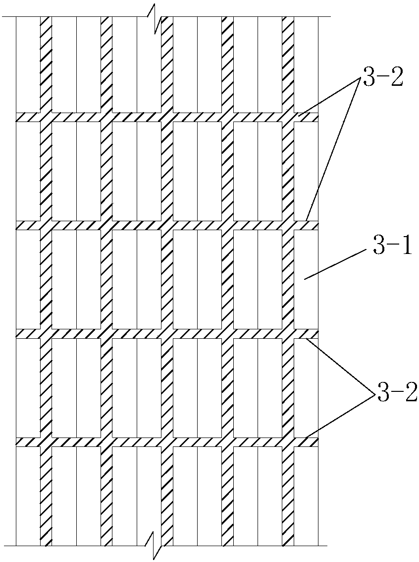
[0105] Such as Figure 11 As shown, the difference between this embodiment and Embodiment 1 is that: the main beam structure 3 includes two longitudinal beams 3-1 and a plurality of cross beams 3-2 arranged between the two longitudinal beams 3-1, One end of the beam 3-2 is connected to a longitudinal beam 3-1, the other end of the beam 3-2 is connected to another longitudinal beam 3-1, and one end of the longitudinal beam 3-1 is connected to the first The support 4 is connected, the other end of the longitudinal beam 3-1 is connected to the second support 9, a bridge deck is paved on the multiple beams 3-2, and the bridge deck is laid on the bridge deck, The lower end of the sling 2 is connected to the longitudinal beam 3-1, and the upper end of the strut 6 is connected to the longitudinal beam 3-1.

[0106] In this embodiment, the stress situation of the combined self-balancing bridge of the arch bridge and the suspension bridge is that the dead load and the live load of the...


PUM


Abstract

The invention discloses a combined self-balancing bridge of an arch bridge and a suspension bridge, which comprises a main girder structure, a bridge deck, two arch rings and two main cables, the main girder structure is connected with the arch rings through suspension cables, and the main cables are connected to the arch rings through struts. The main beam structure is connected, the upper end of the strut is hinged with the main beam structure, and the lower end of the strut is hinged with the main cable. The combined self-balancing bridge combines the force characteristics of arches and cables. The horizontal forces of the arches, cables, and beams are in a self-balancing state, and do not require external horizontal constraints, and do not generate thrust or pull to the outside. The invention also discloses a construction method, which includes abutment or pier construction, support construction, main girder structure construction, arch ring construction, sling construction, bridge deck construction, tension sling, main cable construction, strut This construction method effectively improves the efficiency of bridge completion, reduces the difficulty of construction, and saves the construction period.

Description

technical field [0001] The invention belongs to the technical field of bridges, and in particular relates to a combined self-balancing bridge of an arch bridge and a suspension bridge and a construction method thereof. Background technique [0002] Beam bridges, arch bridges, and cable bridges are different bridge structures, and their stress characteristics are different. The girder bridge is mainly subjected to the bending of the girder, the arch bridge is mainly subjected to the compression of the arch rib, and the cable bridge is mainly subjected to the tension of the cable. The spanning capacity of arch bridges and cable bridges is greater than that of girder bridges, thanks to their ability to give full play to the performance of materials. However, arch bridges mainly under compression will generate horizontal thrust at the arch foot, and the construction of long-span arch bridges requires better geological conditions so that the foundation can resist the horizontal ...

Claims


Application Information

Patent Timeline
Patent Type & Authority Patents(China)
IPC IPC(8): E01D12/00E01D21/00
CPCE01D12/00E01D21/00
Inventor 柴生波任翔宋飞刘克同
Owner XIAN UNIV OF SCI & TECH
Why Eureka
Try Eureka