Smelting furnace heated through combination of heavy oil burning, gas burning and electric arc heating

A heavy oil combustion and gas combustion technology, applied in the field of heating smelting furnaces and smelting furnaces, can solve the problems of unstable combustion, control of the temperature in the furnace, and narrow applicability of raw materials, so as to speed up smelting and reduction, and achieve a reasonable and reasonable rate. The effect of controlling cost and avoiding oxidation phenomenon

Pending Publication Date: 2017-03-15
JIANGSU PROVINCE METALLURGICAL DESIGN INST
View PDF8 Cites 3 Cited by
  • Summary
  • Abstract
  • Description
  • Claims
  • Application Information

AI Technical Summary

Problems solved by technology

[0004] (1) In the smelting furnace, on the one hand, because the hot air flow or even the flame in the heating furnace enters the smelting furnace furnace to directly spray the graphite electrode, the electrode material will be washed away and the electrode consumption will be accelerated; on the other hand, the hot air flow will travel in the smelting furnace If the electrode is blocked on the path, it will cause the air flow to be disturbed
[0005] (2) A large amount of gas will be produced during the metal oxide reduction process, and a large amount of foamy slag will inevitably be produced. After floating, these foamy slag will be driven by the hot air flow that enters the hearth of the smelting furnace through the heating furnace and will block the ventilation with the airflow pipeline, resulting in poor production
[0006] (3) In the heating furnace, the precipitated gas in the smelting furnace is mainly used as fuel gas, and the amount of its generation will fluctuate greatly with the changes in the ratio of materials, coal, coke, etc., resulting in combustion instability and affecting the temperature in the furnace control
Due to the uncontrollable amount of combustible gas, it may cause an explosion accident
[0007] (4) Combustible gas and combustion-supporting air are burned in the heating furnace instead of directly in the furnace of the melting furnace, which inevitably causes heat loss and the heat utilization rate is not high.
[0009] (1) It has the inherent disadvantages of gas-fired smelting furnaces, using radiation heat transfer, low thermal efficiency, difficult to achieve a higher molten pool, low bed utilization, and difficult to achieve large-scale
[0010] (2) It is mainly aimed at the smelting of aluminum ingots, and the applicability of raw materials is narrow. When processing materials with a large amount of slag, since the slag will float above the liquid phase of the metal, and the thermal conductivity of the slag itself is very poor, it will It greatly blocks the conduction of heat from the furnace to the metal phase, resulting in poor mass transfer and heat transfer on the contact surface between the hot metal and the slag, which is likely to cause difficulty in separating the hot metal from the slag, resulting in a decrease in the metal recovery rate. poor production efficiency
[0012] (1) The electrode is still used as the heating element, so its energy consumption is still high;
[0013] (2) It is not possible to adopt different melting and separation methods in different melting sections, so the energy utilization efficiency is not high

Method used


Image

  • Smelting furnace heated through combination of heavy oil burning, gas burning and electric arc heating
  • Smelting furnace heated through combination of heavy oil burning, gas burning and electric arc heating
  • Smelting furnace heated through combination of heavy oil burning, gas burning and electric arc heating

Examples


specific Embodiment approach 1

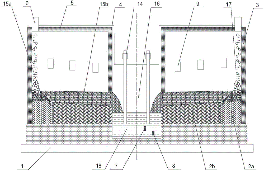
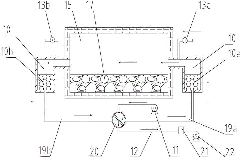
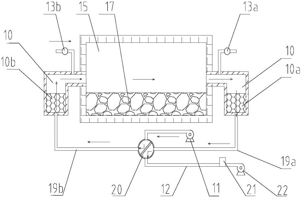
[0048] A heavy oil combustion, gas and electric arc combined heating smelting furnace, its structure is as follows figure 1 Shown: including furnace foundation 1, refractory material furnace bottom 2a, 2b, furnace body side wall 3 made of refractory bricks and refractory material with built-in cooling copper water jacket, partition wall 4 between the melting zone and the settlement zone, Furnace roof 5 located above the furnace, feed inlet 6 located above the furnace roof in the melting zone, slag outlet 7 and hot metal outlet 8 located below the settling zone, 4 sets of heat storage located on opposite walls of the melting zone Type burner burner 9, regenerator 10a, 10b inside regenerator 10, blower 11, flue gas pipeline 12, gas pipeline 13a, 13b, graphite electrode 14 placed on the furnace roof of the settling zone.

[0049] The melting furnace is divided into a melting zone 15 and a settling zone 16. The melting zone 15 is further divided into a melting zone 15a and a melti...

specific Embodiment approach 2

[0054] A heavy oil combustion, gas and electric arc combined heating smelting furnace, its structure is as follows figure 1 Shown: including furnace foundation 1, refractory material furnace bottom 2a, 2b, furnace body side wall 3 made of refractory bricks and refractory material with built-in cooling copper water jacket, partition wall between melting zone 15 and settlement zone 16 4. Furnace roof 5 above the furnace, feed inlet 6 above the furnace roof in melting zone 15, slag outlet 7 and hot metal outlet 8 below settling zone 16, located on opposite walls of melting zone 15 3 sets of regenerative burner burners 9, regenerators 10a, 10b inside the regenerator 10, blower 11, flue gas pipeline 12, gas pipelines 13a, 13b, and graphite electrodes 14 placed on the roof of the settling zone.

[0055] The melting furnace can be divided into a melting zone 15 and a settling zone 16. The melting zone 15 is further divided into a melting zone 15a and a melting zone 15b. The melting z...

specific Embodiment approach 3

[0060] A heavy oil combustion, gas and electric arc combined heating smelting furnace, its structure is as follows figure 1 Shown: including furnace foundation 1, refractory material furnace bottom 2a, 2b, furnace body side wall 3 made of refractory bricks and refractory material with built-in cooling copper water jacket, partition wall between melting zone 15 and settlement zone 16 4. Furnace roof 5 above the furnace, feed inlet 6 above the furnace roof in melting zone 15, slag outlet 7 and hot metal outlet 8 below settling zone 16, located on opposite walls of melting zone 15 10 sets of regenerative burner burners 9, regenerators 10a, 10b inside the regenerator 10, blower 11, flue gas pipeline 12, gas pipelines 13a, 13b, graphite electrodes 14 placed on the roof of the settling zone.

[0061] The melting furnace can be divided into a melting zone 15 and a settling zone 16. The melting zone 15 is further divided into a melting zone 15a and a melting zone 15b. The melting zone...


PUM


Abstract

The invention discloses a smelting furnace heated through combination of heavy oil burning, gas burning and electric arc heating. The smelting furnace comprises a furnace body arranged on a furnace base, the furnace body comprises a side wall, a furnace top, and a fire resistant furnace bottom arranged on the furnace base; a hearth of the furnace body is divided into two parts including a smelting area and a settling area, a furnace bottom of the settling area is lower than a furnace bottom of the smelting area, the furnace bottom of the smelting area adopts an inclined type, one end, adjacent to the settling area, of the smelting area tilts down and is communicated with the settling area, a feed port is formed in a furnace top at one end, far from the settling area, of the smelting area, burners are arranged on opposite two side walls in the smelting area, a graphite electrode penetrating through the furnace top is arranged on the settling area, and a slag discharge port and a hot metal discharge port are respectively formed in the bottom of the settling area. The smelting furnace combines the advantages of gas burning heating and electric arc heating, and has the advantages of low smelting cost, environmental friendliness, high product quality, high handling capacity of single furnace, wide applicability of raw materials, high recovery rate and the like.

Description

technical field [0001] The invention relates to a smelting furnace, in particular to a combined heating smelting furnace of heavy oil combustion, gas combustion and electric arc, which belongs to the field of heating smelting furnaces. Background technique [0002] At present, blast furnaces and electric furnaces are usually used to separate slag and iron from iron-containing materials. Blast furnace is a type of vertical furnace, which is suitable for processing oxidized pellets or sintered ore, and coke is used as raw material. When using it for ironmaking, there are good technical and economic indicators, simple process, large production capacity, and labor production efficiency. High, low energy consumption, etc., but the blast furnace also has the disadvantages of high requirements for the furnace materials, the need to use coking coal, high energy consumption and low energy utilization efficiency; the electric furnace converts the electric energy in the furnace into he...

Claims


Application Information

Patent Timeline
Patent Type & Authority Applications(China)
IPC IPC(8): F27B14/06F27D17/00F27D1/04
CPCF27B14/06F27D1/045F27D17/004F27D2001/047
Inventor 吴道洪刘占华陈文亮王欣曹志成薛逊
Owner JIANGSU PROVINCE METALLURGICAL DESIGN INST
Why Eureka
Try Eureka