Self-powered detector insulation resistance online monitoring method and monitoring device
- Summary
- Abstract
- Description
- Claims
- Application Information
AI Technical Summary
Problems solved by technology
Method used
Image
Examples
Embodiment 1
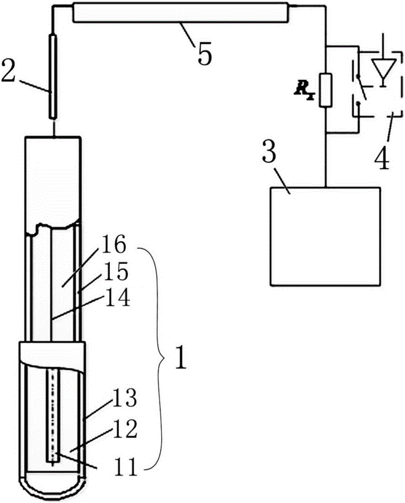
[0028] Self-sufficient detector insulation resistance online monitoring device, such as figure 1 As shown, it includes the self-powered detector body 1, the signal lead-out line 2 connected with the signal core wire in the self-powered detector body 1, and the series resistor R connected in series on the signal lead-out line 2 x , and a current detection device 3 for detecting the current intensity on the signal lead-out line 2; the series resistance R x A control switch 4 is connected in parallel on the top.
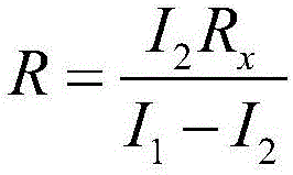
[0029] The self-powered detector insulation resistance online monitoring device of this embodiment is made by the above-mentioned connection method, and the self-powered detector body 1 of the above-mentioned self-powered detector insulation resistance online monitoring device is placed in the core, so that the self-powered detector body In the working state, the resistance value of the insulation resistance R of the self-powered detector body 1 is detected by the foll...
Embodiment 2
[0034] The difference between this embodiment and Embodiment 1 is that this embodiment optimizes the type of control switch 4 and adds a shielding layer 5, which is set as follows:
[0035] In this embodiment, the control switch 4 is an electronic switch, and the electronic switch communicates with the control terminal on the electronic switch through the controller to control the switching of the electronic switch. The self-powered detector body 1 is connected in series with a resistor R x A shielding layer 5 is provided on the signal lead-out lines 2 between them, such as figure 1 shown.
Embodiment 3
[0037] The difference between this embodiment and Embodiment 1 is that the specific structure of the self-powered detector body 1 is given in this embodiment, which is set as follows:
[0038] The self-powered detector body 1 includes a central emitter 11 , an insulator 12 , and a collector 13 coaxially arranged from inside to outside, and a signal core wire 14 communicating with the central emitter 11 . The signal core wire 14 is provided with an armored shell 15 , and an insulating material 16 is disposed between the armored shell 15 and the signal core wire 14 .
PUM
 Abstract
Description
Claims
Application Information
 - R&D
- Intellectual Property
- Life Sciences
- Materials
- Tech Scout
- Unparalleled Data Quality
- Higher Quality Content
- 60% Fewer Hallucinations
Browse by: Latest US Patents, China's latest patents, Technical Efficacy Thesaurus, Application Domain, Technology Topic, Popular Technical Reports.
© 2025 PatSnap. All rights reserved.Legal|Privacy policy|Modern Slavery Act Transparency Statement|Sitemap|About US| Contact US: help@patsnap.com


