drone camera lens
A camera lens and UAV technology, applied in the lens field, can solve the problems that affect the imaging quality of the camera lens of the drone, the camera lens cannot adapt to the temperature environment, and the temperature has a great influence on the camera lens, so as to ensure the quality of resolution, high Quality Resolution, Lightweight Effects
- Summary
- Abstract
- Description
- Claims
- Application Information
AI Technical Summary
Problems solved by technology
Method used
Image
Examples
Embodiment 1
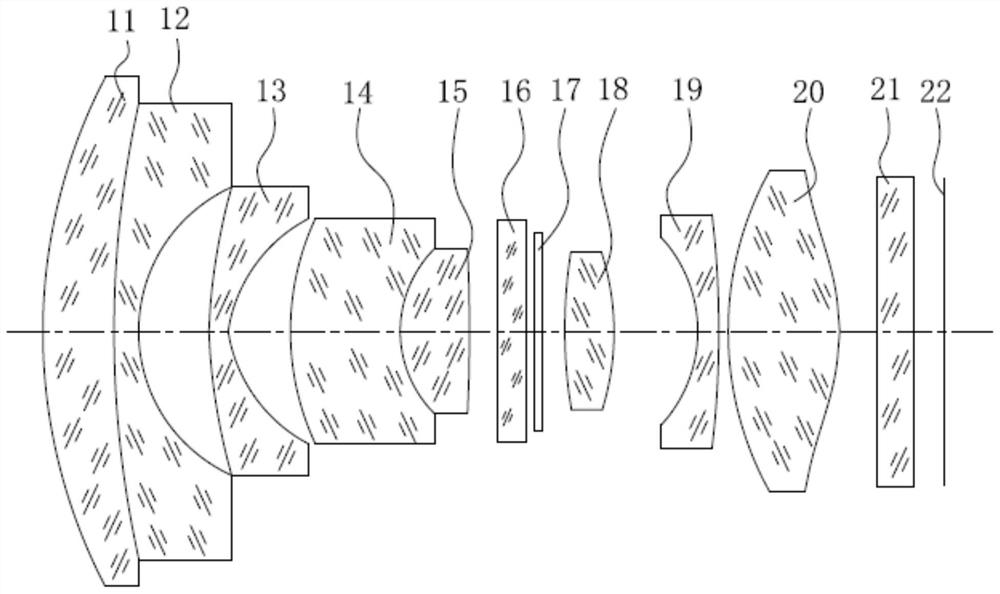
[0063] See Figure 1a , shown is a schematic diagram of the cross-sectional structure of the drone camera lens in a first embodiment of the present invention, from the object side to the imaging surface in turn comprising a first lens with a positive focal length 11, a second lens having a negative focal length 12, a third lens having a negative focal length 13, a fourth lens having a negative focal length 14, a fifth lens having a positive focal length 15, a filter 16, a gloss 17, a sixth lens having a positive focal length 18, a seventh lens having a negative focal length 19, a eighth lens having a positive focal length 20, Cover glass 21 and imaging surface 22. Wherein, the optical center of each lens is located in the same straight line, and all the lenses of the UAV camera lens are plated with a high transmittance multilayer film.
[0064]Specifically, the first lens 11 is a meniscus and concave side facing the imaging surface of the glass spherical lens, the second lens 12 is...
Embodiment 2
[0108] See Figure 2a , shown is a schematic diagram of the cross-sectional structure of the UAV camera lens in the second embodiment of the present invention, the UAV camera lens in the present embodiment and the UAV camera lens in the first embodiment are substantially the same, the difference is that the relevant parameters of each lens of the UAV camera lens in the present embodiment and the relevant parameters of the each lens of the UAV camera lens in the first embodiment are different.
[0109] Referring to Table 3, the relevant parameters of each lens of the UAV camera lens shown in the present embodiment.
[0110] Table 3:
[0111]
[0112]
[0113] Referring to Table 4, the relevant parameters of the aspheric surface of the UAV camera lens shown in the present embodiment.
[0114] Table 4:
[0115]
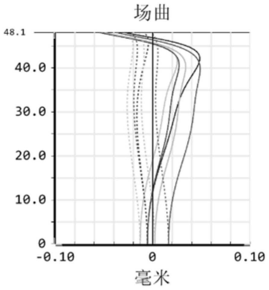
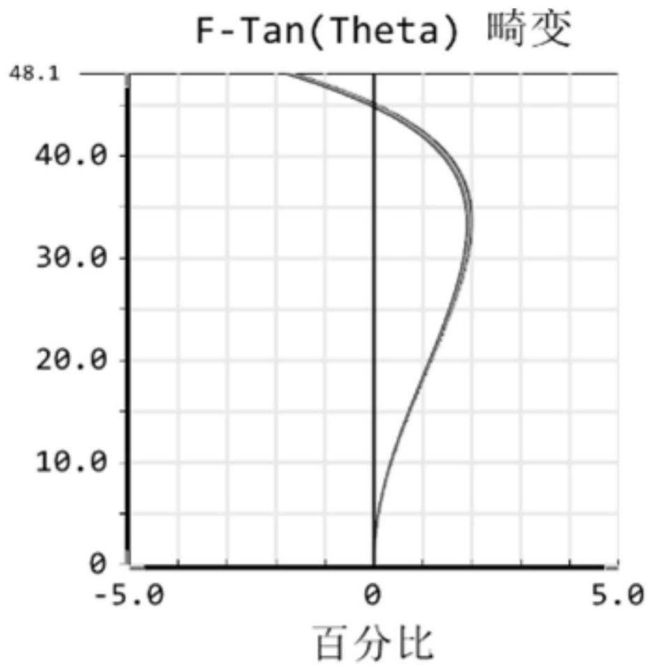
[0116] SeeFigure 2b , shown in the present embodiment of the UAV camera lens of the field curve graph, refer to Figure 2c , shown in the present embodiment of the UAV c...
Embodiment 3
[0118] See Figure 3a , shown is a schematic diagram of the cross-sectional structure of the UAV camera lens in the third embodiment of the present invention, the UAV camera lens in the present embodiment is substantially the same as the UAV camera lens in the first embodiment, the difference is that the UAV camera lens in the present embodiment is based on the first embodiment, the first lens 11 and the second lens 12 are independently separated, the two are used separately, rather than combined into a glued lens, At the same time, the relevant parameters of each lens of the UAV camera lens in the present embodiment and the relevant parameters of each lens of the UAV camera lens in the first embodiment are different.
[0119] Referring to Table 5, the relevant parameters of each lens of the UAV camera lens shown in the present embodiment.
[0120] Table 5:
[0121]
[0122]
[0123] Referring to Table 6, the relevant parameters of the aspheric surface of the UAV camera lens sh...
PUM
 Abstract
Description
Claims
Application Information
 - R&D
- Intellectual Property
- Life Sciences
- Materials
- Tech Scout
- Unparalleled Data Quality
- Higher Quality Content
- 60% Fewer Hallucinations
Browse by: Latest US Patents, China's latest patents, Technical Efficacy Thesaurus, Application Domain, Technology Topic, Popular Technical Reports.
© 2025 PatSnap. All rights reserved.Legal|Privacy policy|Modern Slavery Act Transparency Statement|Sitemap|About US| Contact US: help@patsnap.com


