

Anion air purifier circuit employing design of adjustable voltage stabilization circuit
An air purifier and circuit design technology, applied in the field of air purification, can solve problems such as dust, poor movement, etc., and achieve the effect of scientific and reasonable design and convenient use
- Summary
- Abstract
- Description
- Claims
- Application Information
AI Technical Summary
Problems solved by technology
Method used
Image

Examples
Embodiment 1
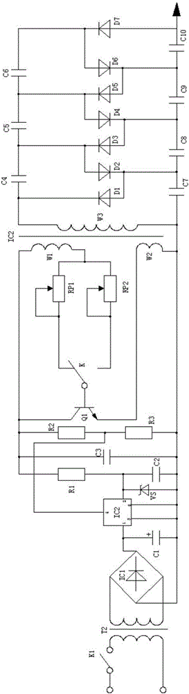
[0046] A negative ion air purifier circuit designed with an adjustable voltage stabilizing circuit, using a DC power supply designed with a voltage stabilizing chip (a voltage stabilizing chip with an adjustable function) to supply power for an inductive oscillator and a voltage doubler rectifier circuit, Designed based on the existing mature integrated voltage regulation technology, it can provide variable voltage regulation for the negative ion air purifier circuit, and an RCπ filter for filtering ripple voltage is set in the DC power supply to stabilize the voltage The output power supply is further filtered so that the DC power supply can provide a working power supply without ripple voltage, so that the inductive oscillator and the voltage doubler rectifier circuit can operate in a stable power supply environment, avoiding the ripple voltage caused by Circuit operation is unstable, affecting the stabilization of negative air ions, such as figure 1 , figure 2 As shown, t...
Embodiment 2
[0056] This embodiment is further optimized on the basis of the above-mentioned embodiments. Further, in order to better realize the present invention, an RCπ-type power filter can be used to filter out the power supply voltage after being stabilized by a voltage stabilizing chip, such as figure 1 , figure 2 As shown, the following arrangement structure is adopted in particular: the RCπ-type power filter includes a filter capacitor C2, a resistor R1 and a filter capacitor C3, and the first end of the capacitor C2 is respectively connected to the first end of the resistor R1 and the 2 pins of the voltage stabilizing chip IC2. The second end of the resistor R1 is respectively connected to the non-common end of the resistor R2 and the first end of the capacitor C3, and the second end of the capacitor C2 is connected to the second end of the capacitor C3 and grounded.
Embodiment 3
[0058] This embodiment is further optimized on the basis of any of the above-mentioned embodiments. Further, in order to better realize the present invention, bridge rectification can be used to rectify the AC power after structural transformation, and then use the filter capacitor to filter out the The ripple voltage included, and the voltage regulation comparator circuit is used to stabilize the output, and provide a safe and reliable DC voltage for the subsequent stage, such as figure 1 , figure 2As shown, the following arrangement structure is adopted in particular: a switch K1, a power transformer T2, a bridge rectifier stack IC1 and a filter capacitor C1 are arranged in the voltage transformer rectifier circuit, and the switch K1 is arranged on one end of the primary end of the power transformer T2 , the secondary end of the power transformer T2 is connected to the input end of the bridge rectifier stack IC1, and the output end of the bridge rectifier stack IC1 is conne...
PUM
 Abstract
Description
Claims
Application Information