Electric tool used for pipefitting chamfering

A chamfering, electric technology used in electric tooling. It can solve the problems of low production efficiency and poor product quality, and achieve the effect of high production efficiency, convenient operation and good product quality consistency.

Inactive Publication Date: 2017-03-22
荣成康派斯新能源车辆股份有限公司
View PDF6 Cites 2 Cited by
  • Summary
  • Abstract
  • Description
  • Claims
  • Application Information

AI Technical Summary

Problems solved by technology

[0004] In order to overcome the shortcomings of low production efficiency and poor product quality in existing manual grinding and chamfering, the invention provides a pipe fitting with simple structure, convenient operation, good product quality consistency, low worker strength and high production efficiency. Electric tooling for chamfering

Method used


Image

  • Electric tool used for pipefitting chamfering
  • Electric tool used for pipefitting chamfering
  • Electric tool used for pipefitting chamfering

Examples


Embodiment 1

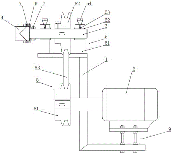
[0025] like figure 1 As shown, an electric tool for pipe chamfering includes a frame 1 , a driving motor 2 , a rotating shaft 3 and a cutter head 4 .

[0026] exist figure 1 Among them, the rotating shaft 3 is rotatably supported on the top of the frame 1 via a support member 5 . The support member 5 includes a bearing seat 51 and a bearing 52 , wherein the bearing seat 51 is fixed on the top of the frame 1 , and the bearing 52 is supported between the rotating shaft 3 and the bearing seat 51 .

[0027] like figure 1 As shown, in order to strengthen the lubrication of the bearing 52, an oil injection hole 53 is opened on the bearing seat 51. The inner end of the oil injection hole 53 communicates with the bearing 52, and an oil cap 54 is threaded on the outer end of the oil injection hole 53. The oil cap 54 blocks the oil injection hole 53 .

[0028] like figure 1 As shown, the cutter head 4 is non-rotatably connected to the end of the rotating shaft 3 through the cutter ...

Embodiment 2

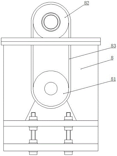
[0036] exist Figure 5 , Image 6 Among them, an electric tooling for pipe chamfering is the same as that of Embodiment 1 in that it includes a frame 1 and a driving motor 2 , and the driving motor 2 is fixed on the bottom of the frame 1 .

[0037] like Figure 5 , Image 6 As shown, it is different from Embodiment 1 in that: there are two rotating shafts 3, which are arranged in parallel, and the two ends of each rotating shaft 3 are respectively supported on the top of the frame 1 through support members 5; The end of 3 is non-rotatably provided with cutter head seat 6 through lock piece 7, and inner chamfering rotary cutter head 41, outer chamfering rotary cutter head 42 are respectively provided with on two cutter head seats 6.

[0038] exist Figure 5 , Image 6 Among them, the transmission part 8 includes a driving pulley 81, two driven pulleys 82 and a transmission belt 83, the driving pulley 81 is non-rotatably assembled on the output shaft of the driving motor 2 ...


PUM


Abstract

The invention discloses an electric tool for pipefitting chamfering. The problems that according to existing manual burr grinding and chamfer finishing, production efficiency is low, and the product quality is poor are solved. The tool comprises a rack, a drive motor, at least one rotating shaft and at least one cutter bit and is characterized in that the rotating shafts are rotatably supported on the top of the rack through supporting parts, the cutter bits are connected to the ends of the rotating shafts in a non-rotation manner through cutter bit bases, the drive motor is fixed to the bottom of the rack, and an output shaft of the drive motor drives the rotating shafts to rotate through a transmission part. The electric tool is simple in structure and convenient to operate; a pipefitting required to be chamfered stretches into the tool bits and makes contact with the tool bits, burr removing and chamfering can be carried out, the product quality consistency is good, the strength of workers is low, and the production efficiency is high.

Description

technical field [0001] The invention relates to a cutting processing device, in particular to an electric tool used for pipe chamfering. Background technique [0002] We know that when a camping RV is camping, a tent is usually used as a shelter for the RV to expand its space. In order to reduce the quality of the tent, most of the tents are shaped by using aluminum alloy pipes with small mass and strong toughness as support rods. During the production process, when the aluminum alloy pipe is sawed and blanked, thorns will be formed at the cutting end of the aluminum alloy pipe. These thorns will not only affect the quality of the product, but also stab users and workers. Therefore, through Removing thorns by chamfering has become an indispensable job. [0003] At present, grinding burrs and trimming chamfers are mainly done manually by workers using files, which has low production efficiency, inconsistent chamfer sizes, and poor product quality. Contents of the inventio...

Claims


Application Information

Patent Timeline
Patent Type & Authority Applications(China)
IPC IPC(8): B23D79/02
CPCB23D79/023
Inventor 王位元
Owner 荣成康派斯新能源车辆股份有限公司
Why Eureka
Try Eureka