
Weld verification method

A verification method, a technology to be verified, applied in the direction of welding equipment, auxiliary welding equipment, welding/cutting auxiliary equipment, etc., can solve problems such as not being able to meet actual needs

Inactive Publication Date: 2017-03-22
SUZHOU VR ROBOT TECH CO LTD
View PDF3 Cites 1 Cited by
  • Summary
  • Abstract
  • Description
  • Claims
  • Application Information

AI Technical Summary

Problems solved by technology

Therefore, the existing methods cannot meet the actual needs.

Method used


Image

  • Weld verification method
  • Weld verification method
  • Weld verification method

Examples


Embodiment Construction

[0028] The details of the present invention can be understood more clearly with reference to the accompanying drawings and the description of specific embodiments of the present invention. However, the specific embodiments of the present invention described here are only for the purpose of explaining the present invention, and should not be construed as limiting the present invention in any way. Under the teaching of the present invention, the skilled person can conceive any possible modification based on the present invention, and these should be regarded as belonging to the scope of the present invention.

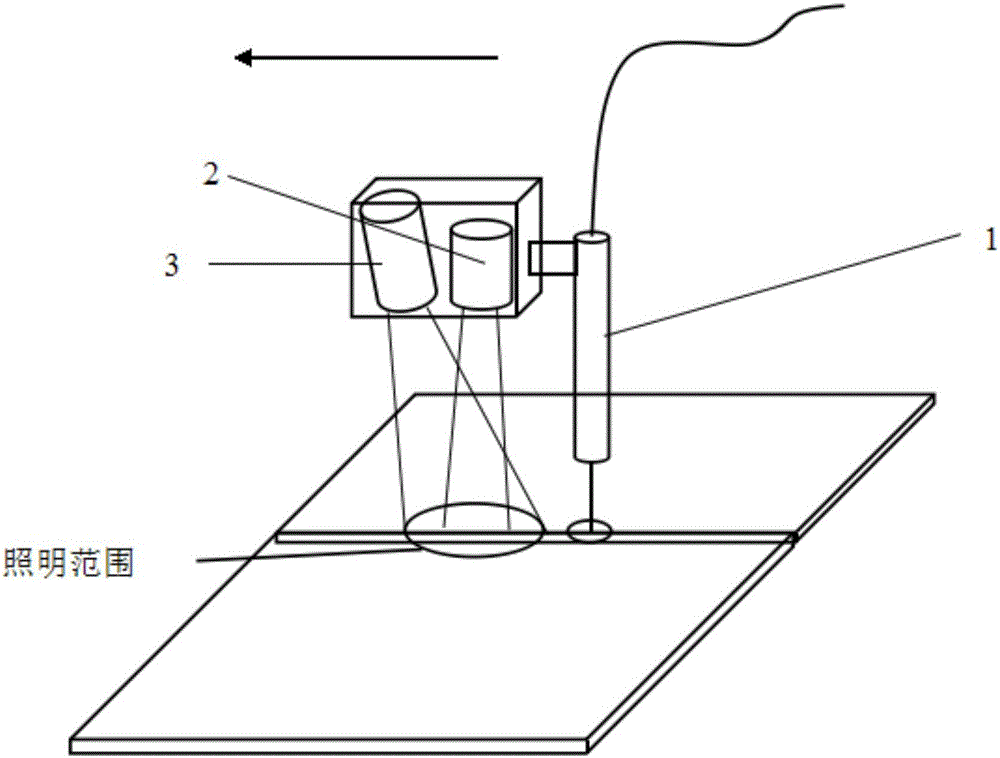
[0029] The invention discloses a welding seam detection method, which comprises the following steps:

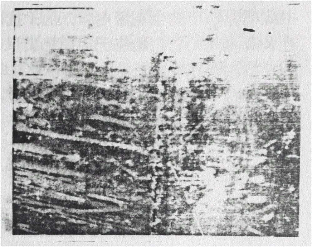
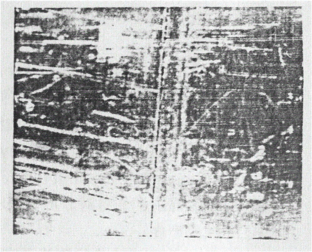
[0030] Get the image of the weld seam;

[0031] In the obtained weld seam image, the row direction of the initial image is roughly perpendicular to the weld seam, and a row is selected every n rows for processing, and a total of m rows are selected. Here m is a positiv...


PUM


Abstract

The invention relates to a verification method for butt weld detection results. The verification method includes the following steps that a weld image and a weld straight line to be verified in the weld image are acquired; q pixel points are selected at the two sides of each row of intersection points with the weld straight line to be verified to form an image subset, the direction of an original image row is generally perpendicular to the weld straight line to be verified, and q is a positive integer which is larger than or equal to 1; all the rows of the image subset are added to obtain an array, the array is subjected to first-order difference, and the positions of the maximum value and the minimum value are found out; and if the maximum value and the minimum value are located at the two sides of the weld straight line to be verified, it is judged that the weld position to be verified is reliable. By the adoption of the method, butt welds (including the welds without gaps and with certain gaps) of sheets under various conditions can be reliably verified, and the phenomenon of recognition failure can be avoided.

Description

technical field [0001] The invention relates to a visual recognition for the butt welding seam of a metal thin plate structure in robot or automatic welding, in particular to a welding seam verification method. Background technique [0002] Gapless butt joints of thin plate structures are widely used in the aerospace industry, and the requirements for automatic identification and tracking of such joints are also very urgent. People have used a variety of methods to study this, such as laser scanning ranging method and light intensity analysis method, image analysis method and electromagnetic sensor method. At present, there is still a large distance between these research work and practical application. Because these methods almost all assume that the joint has a certain gap, misalignment or inclined characteristics, but the actual joint condition is difficult to meet the requirements. For example, existing welds have various butt weld conditions, such as places with a sma...

Claims


Application Information

Patent Timeline
Patent Type & Authority Applications(China)
IPC IPC(8): B23K37/00G06T7/00B23K33/00B23K101/18
CPCB23K37/00B23K33/004G06T7/00
Inventor 张炯
Owner SUZHOU VR ROBOT TECH CO LTD
Learn More