Multi-axis high-speed CNC lathe

A CNC lathe, high-speed technology, applied in the direction of manufacturing tools, other manufacturing equipment/tools, tool holders, etc., can solve the problems of low product processing accuracy, cumbersome and complicated processing process, and reduce production efficiency, so as to avoid excessive cantilever, Improve production efficiency and machining accuracy, and improve production efficiency

Inactive Publication Date: 2018-11-23
DONGGUAN HONGJINSHUN MACHINERY MFG
View PDF6 Cites 0 Cited by
  • Summary
  • Abstract
  • Description
  • Claims
  • Application Information

AI Technical Summary

Problems solved by technology

[0002] When the existing CNC inclined bed lathes turn cylindrical workpieces such as motor rotors and other products, the outer circle turning process and the chamfering process are carried out separately, and the tool change operation needs to be suspended in the middle, so at least two processes are required to complete the outer circle. Round machining and chamfering process, which makes the whole machining process cumbersome and complicated, requiring frequent tool changes, which not only reduces production efficiency but also easily increases machining errors
In addition, in the process of processing, it is necessary to minimize the swing of the workpiece during high-speed rotation to reduce errors, so an auxiliary centering device is needed. However, the existing auxiliary centering devices often have too long cantilever and poor stability during use. Cause product processing accuracy is not high

Method used


Image

  • Multi-axis high-speed CNC lathe
  • Multi-axis high-speed CNC lathe
  • Multi-axis high-speed CNC lathe

Examples


Embodiment Construction

[0014] The present invention will be further described below in conjunction with specific embodiments and accompanying drawings.

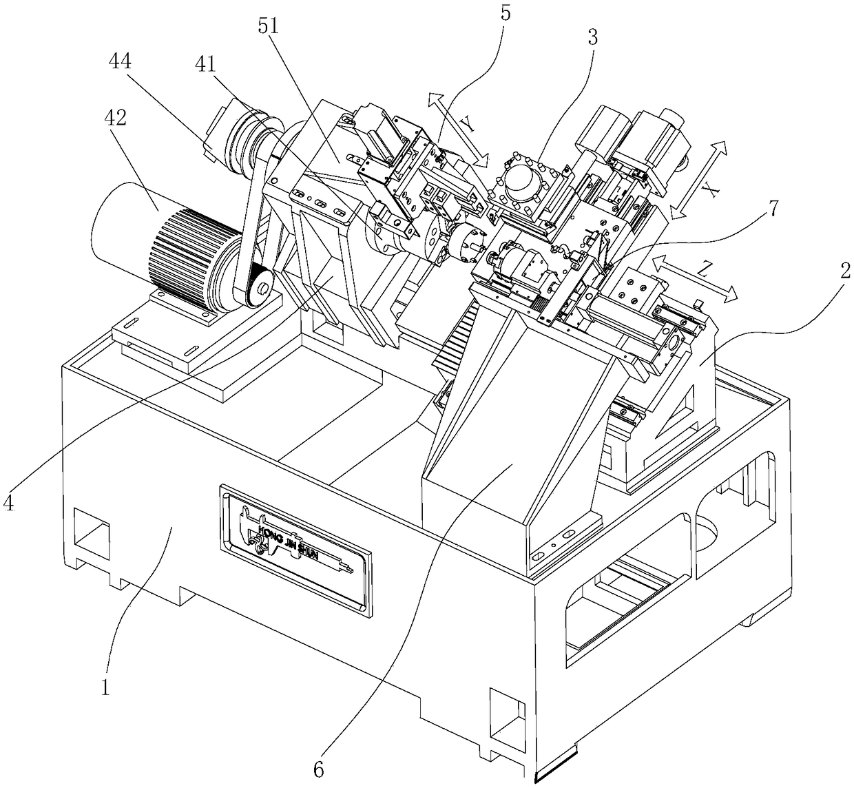
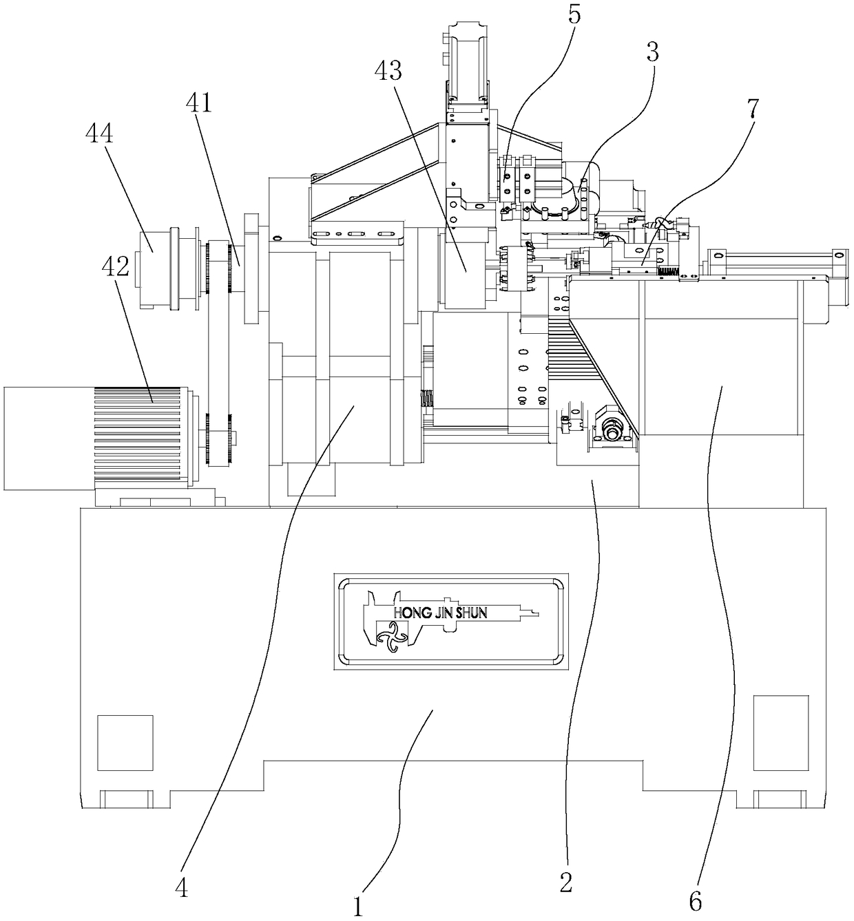
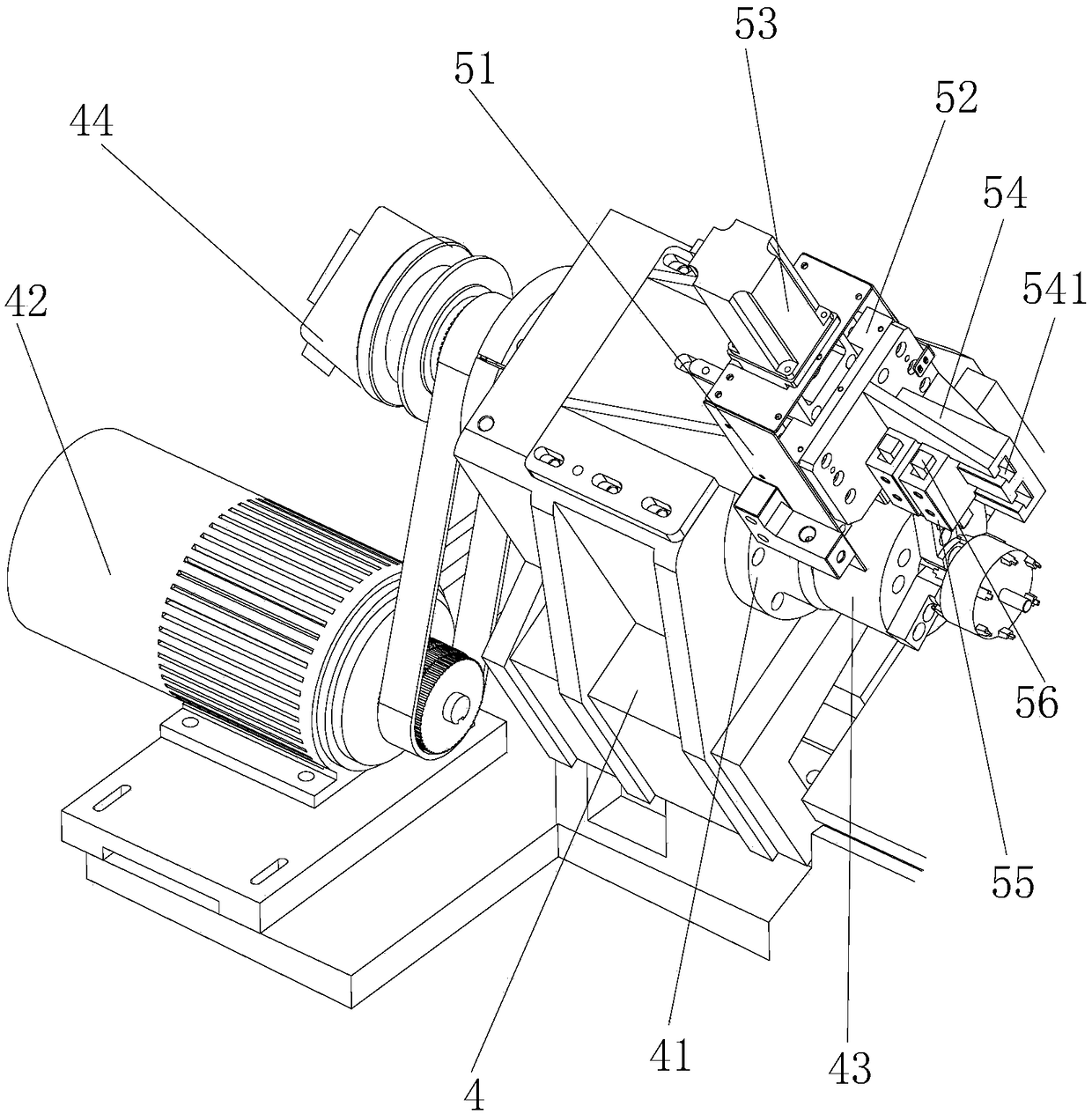
[0015] like Figure 1-Figure 5 As shown, what the present invention described is a kind of multi-axis high-speed numerical control lathe, and it comprises a slanted bed lathe body, and this slanted bed lathe body has a main frame 1 and a work surface and the main frame 1 is inclined setting (usually 60° or 45°) of the inclined bed assembly 2, the first slide table 21 (i.e. cross slide) and the first sliding table 21 (i.e. cross slide) which moves in the horizontal direction (i.e. Z axis) along its working surface are installed on the inclined bed assembly 2 The first slide table drive mechanism is equipped with a second slide table 22 (i.e. the X-axis carriage) and a second slide table drive mechanism 23 on the first slide table 21, and the second slide table is on the first slide table 21 along with The inclined bed assembly 2 moves in the vertic...


PUM


Abstract

The invention relates to a multi-shaft high-speed numerically controlled lathe. The multi-shaft high-speed numerically controlled lathe comprises a slant bed lathe body which is provided with a main machine and a slant bed body assembly. A four-station electric tool carrier and a lathe spindle are mounted on the slant bed body assembly, wherein an additional machining shaft system assembly which is arranged perpendicular to the lathe spindle is further mounted on a spindle box; a second fixed seat is arranged on the lateral side of the slant bed body assembly on the main machine; and an auxiliary centering assembly opposite to the lathe spindle is mounted above the second fixed seat. According to the multi-shaft high-speed numerically controlled lathe provided by the invention, a machining shaft is additionally arranged; on the basis of the original machining shaft which machines an excircle, the additionally arranged machining shaft can perform operations such as chamfering and groove milling simultaneously, so that the production efficiency and the machining precision are greatly improved; the auxiliary centering assembly is a three-finger pneumatic finger, and a guide rail and sliding tables are arranged at the bottom of the three-finger pneumatic finger, so that a cantilever of the centering assembly can be prevented from being overlong, and the stability of the centering assembly is greatly improved.

Description

Technical field: [0001] The invention relates to the technical field of processing machine tools, in particular to a multi-axis high-speed numerical control lathe. Background technique: [0002] When the existing CNC inclined bed lathes turn cylindrical workpieces such as motor rotors and other products, the outer circle turning process and the chamfering process are carried out separately, and the tool change operation needs to be suspended in the middle, so at least two processes are required to complete the outer circle. Round machining and chamfering process, which makes the whole machining process cumbersome and complicated, requiring frequent tool changes, which not only reduces production efficiency but also easily increases machining errors. In addition, in the process of processing, it is necessary to minimize the swing of the workpiece during high-speed rotation to reduce errors, so an auxiliary centering device is needed. However, the existing auxiliary centering ...

Claims


Application Information

Patent Timeline
Patent Type & Authority Patents(China)
IPC IPC(8): B23P23/02B23B29/32
CPCB23B29/32B23P23/02
Inventor 李良平肖永华李新连胡德兵
Owner DONGGUAN HONGJINSHUN MACHINERY MFG
Why Eureka
Try Eureka