
Novel sheet metal cutting machine

A metal sheet and cutting machine technology, which is applied to metal processing machinery parts, metal processing equipment, large fixed members, etc., can solve the problems of complex cutting process, unsafe metal sheet, difficult manual operation, etc., and achieve simple cutting process, High cutting efficiency and easy manual operation

Inactive Publication Date: 2017-03-22
苏州瑞升利金属制品有限公司
View PDF8 Cites 2 Cited by
  • Summary
  • Abstract
  • Description
  • Claims
  • Application Information

AI Technical Summary

Problems solved by technology

[0003] The cutting process of the traditional sheet metal cutting machine is complex, manual operation is very difficult, the efficiency of sheet metal cutting is very low, and the metal is prone to slipping during cutting, which brings great insecurity to our sheet metal cutting factor

Method used


Image

  • Novel sheet metal cutting machine
  • Novel sheet metal cutting machine
  • Novel sheet metal cutting machine

Examples


Embodiment 1

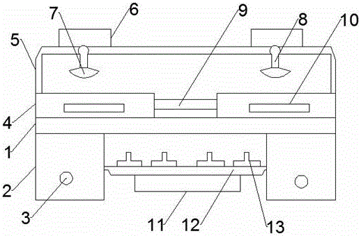
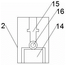
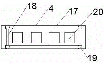
[0017] see figure 1 , figure 2 and image 3 , the present invention provides a technical solution: a novel sheet metal cutting machine, comprising a load-bearing plate 1, two support legs 2 fixed on the lower end of the load-bearing plate 1, and two cutting tables 3 installed on the upper end of the load-bearing plate 1, The No. 3 driver 14 is installed in the two support legs 2, and the No. 3 driver 14 is connected with an electric control lifting rod 15 through a speed governor 16. The top of the electric control lifting rod 15 passes through the load-bearing plate 1 and is connected to the cutting table 4. Control the height of the cutting table 4 and the angle of cutting the sheet metal. A knob 3 is installed on the support leg 2. The knob 3 is electrically connected to the governor 16. The upper ends of the two cutting tables 4 are connected by a fixed frame 5, fixed Two No. 1 drivers 6 are installed on the top of the frame 5, and the bottom of the No. 1 driver 6 is co...

Embodiment 2

[0019] see figure 1 , figure 2 and image 3 , the present invention provides another technical solution: limit the position of the metal plate placed on the cutting table 4 by a limit rod 18, rotate the knob 3, control the governor 16 to adjust the speed, and the second driver 14 drives the motor Control the lifting rod 15 to lift, thereby the height of the cutting table 4 is adjusted, the expansion and contraction of the telescopic device 8 can be controlled by the No. 1 driver 6, and the cutting tool 7 can quickly cut the metal sheet, which can be cut in two A metal plate or a metal plate is placed on the platform 4, and the two supporting legs 2 are connected by a fixed plate 12. Four grinders 13 are installed on the upper end of the fixed plate 12, and the second driver 11 is fixed on the lower end of the fixed plate 12. , the grinder 13 is electrically connected to the No. 2 driver 11, and the No. 2 driver 11 can drive the grinder 13 to work, and can grind the cut meta...


PUM


Abstract

The invention discloses a novel sheet metal cutting machine. The novel sheet metal cutting machine comprises a bearing plate, two supporting legs fixed to the lower end of the bearing plate and two cutting tables installed at the upper end of the bearing plate; third drivers are installed in the two supporting legs and are connected to electrically-controlled lifting rods through speed regulators, the electrically-controlled lifting rods penetrate through the bearing plate to be connected to the cutting tables, the supporting legs are provided with rotary knobs, and the rotary knobs are electrically connected to the speed regulators; the upper ends of the two cutting tables are connected through a fixed frame, two first drivers are installed at the top of the fixed frame, the bottoms of the first drivers are connected to cutting tools through telescopic devices, and the cutting tools face the surfaces of the cutting tables; and sliding rails are arranged on the transverse edges on the surface of each cutting table, and two limiting rods are installed between the sliding rails. The cutting process is simple, manual operation is easy, the cutting efficiency of sheet metal is high, and the metal is prevented from sliding in the cutting process.

Description

technical field [0001] The invention relates to the technical field of sheet metal cutting, in particular to a novel sheet metal cutting machine. Background technique [0002] The earliest boards were solid wood boards for carpentry, which were used to make furniture or other living facilities. Nowadays, with the development of science and technology, the definition of boards is very broad. There are boards of different materials in furniture manufacturing, construction industry, processing industry, etc. Among them, metal The board has been greatly welcomed because of its own advantages. [0003] The cutting process of the traditional sheet metal cutting machine is complex, manual operation is very difficult, the efficiency of sheet metal cutting is very low, and the metal is prone to slipping during cutting, which brings great insecurity to our sheet metal cutting factor. Contents of the invention [0004] In view of the above problems, the present invention provides a...

Claims


Application Information

Patent Timeline
IPC IPC(8): B23P23/04B23Q3/06B23Q1/25
CPCB23P23/04B23Q1/25B23Q3/062
Inventor 吴明伟曾志红
Owner 苏州瑞升利金属制品有限公司
Learn More