Automobile decoupling distributed brake system electric-hydraulic combined braking execution mechanism

A technology of braking system and actuator, applied in the direction of brake transmission, brake, cooling brake, etc., can solve the problem of insufficient use of braking energy, etc., to improve braking performance and safety performance, good work reliability and Anti-failure ability, the effect of improving thermal decay resistance

Inactive Publication Date: 2017-03-22
JIANGSU UNIV OF TECH
View PDF10 Cites 3 Cited by
  • Summary
  • Abstract
  • Description
  • Claims
  • Application Information

AI Technical Summary

Problems solved by technology

[0006] The purpose of the present invention is to overcome the defect that the electro-hydraulic hybrid braking system in the prior art cannot make full use of the braking energy, and provide an electro-hydraulic hybrid braking actuator of the automobile decoupling distributed braking system

Method used


Image

  • Automobile decoupling distributed brake system electric-hydraulic combined braking execution mechanism
  • Automobile decoupling distributed brake system electric-hydraulic combined braking execution mechanism
  • Automobile decoupling distributed brake system electric-hydraulic combined braking execution mechanism

Examples


Embodiment 1

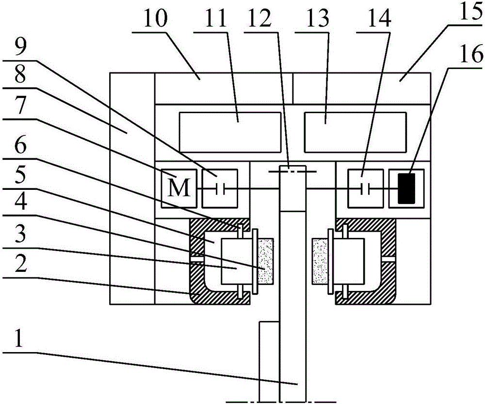
[0028] Such as figure 1 As shown, an electro-hydraulic composite brake actuator of an automobile decoupling distributed braking system includes a brake drive part 26 and a hydraulic brake actuator part 25. In order to save installation space, the brake drive part 26 in this embodiment Set inside the hydraulic brake execution part 25, the brake drive part 26 includes a brake disc 1, an oil pump clutch 14, a motor clutch 9, a battery pack 10 and an electronic control unit 15, the active part of the oil pump clutch 14 and The active parts of the motor clutch 9 are all in transmission connection with the brake disc 1. Specifically, the outer ring of the brake disc 1 is provided with a ring gear, and the pinion 12 meshes with the ring gear, so that the brake disc 1 is connected to the motor through the pinion 12. The clutch 9 and the oil pump clutch 14 are in transmission connection; the driven part of the oil pump clutch 14 is in transmission connection with the rotor of the oil p...

Embodiment 2

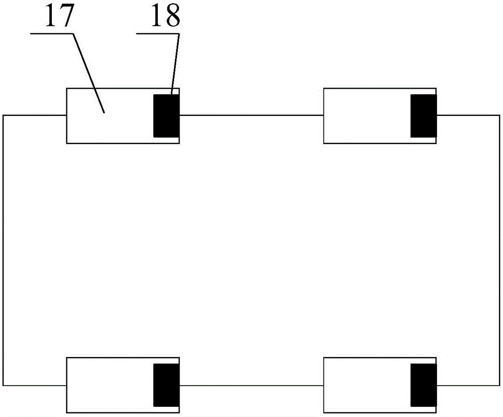
[0036] The difference from Example 1 is that, as Figure 4~6 As shown, the brake drive part 26 is arranged side by side with the hydraulic brake actuator part 25, and the two parts are integrated. Its working principle is the same as that in Embodiment 1. Compared with the arrangement in Embodiment 1, the arrangement in this embodiment can effectively reduce the overall height of the brake actuating structure.


PUM


Abstract

The invention relates to the technical field of vehicle brake, in particular to an automobile decoupling distributed brake system electric-hydraulic combined braking execution mechanism. The automobile decoupling distributed brake system electric-hydraulic combined braking execution mechanism comprises a brake drive part and a hydraulic brake execution part. The brake drive part comprises a brake plate, an oil pump clutch, a motor clutch, a battery pack and an electronic control unit. A driving part of the oil pump clutch and a driving part of the motor clutch are both in transmission connection with the brake plate. A driven part of the oil pump clutch is in transmission connection with a rotor of an oil pump. A driven part of the motor clutch is in transmission connection with a rotor of a motor. The motor is electrically connected with the battery pack. An electronic control element controls the motor to charge the battery pack or controls the battery pack to supply power to the motor. The electronic control element controls the motor clutch and the oil pump clutch to be connected or disconnected. The hydraulic brake execution part is matched with the brake plate, and the oil pump serves as a power source of the hydraulic brake execution part. It is unnecessary to arrange hydraulic pipelines for a whole vehicle, and the dynamic response is rapid. Emergency brake of the vehicle is achieved under driving of brake energy of the vehicle.

Description

technical field [0001] The invention relates to the technical field of vehicle braking, in particular to an electro-hydraulic composite braking actuator of an automobile decoupling distributed braking system. Background technique [0002] The braking system is one of the important components of the automobile chassis, which is directly related to the comprehensive performance of the automobile and the safety of life and property. Although the traditional hydraulic and pneumatic braking systems can meet the requirements of the existing braking regulations, there are complex pipeline arrangements, relying on vacuum booster devices, slow braking response speed, non-active adjustment of braking torque, and difficulty in matching Other deficiencies such as system integration control are not suitable for the development requirements of automobiles, especially electric vehicle chassis integration control. [0003] The electronically controlled braking system realizes the decouplin...

Claims


Application Information

Patent Timeline
IPC IPC(8): B60T13/68B60T5/00
CPCB60T13/686B60T5/00
Inventor 贝绍轶赖晓杰施伟王忠收邵超超童欣卞军军王奎洋
Owner JIANGSU UNIV OF TECH
Why Eureka
Try Eureka