
T-shaped empennage and aircraft with same

A tail and aircraft technology, applied in the aviation field, can solve the problems of reduced trimming capability of the horizontal tail, affecting the efficiency of the horizontal tail, unreasonable design of the joints, etc., so as to reduce mutual interference, simplify redundant design, and increase the efficiency of the horizontal tail.

Inactive Publication Date: 2017-03-22
SF TECH
View PDF6 Cites 5 Cited by
  • Summary
  • Abstract
  • Description
  • Claims
  • Application Information

AI Technical Summary

Problems solved by technology

[0003] However, in the T-tail layout of traditional aircraft, the horizontal tail is still greatly affected by the flow field of the fuselage, which reduces the trimming ability of the horizontal tail; at the same time, the design of the connection between the horizontal tail and the vertical tail is unreasonable and redundant Too much, affecting the efficiency of the horizontal stabilizer

Method used


Image

  • T-shaped empennage and aircraft with same
  • T-shaped empennage and aircraft with same
  • T-shaped empennage and aircraft with same

Examples


Embodiment 1

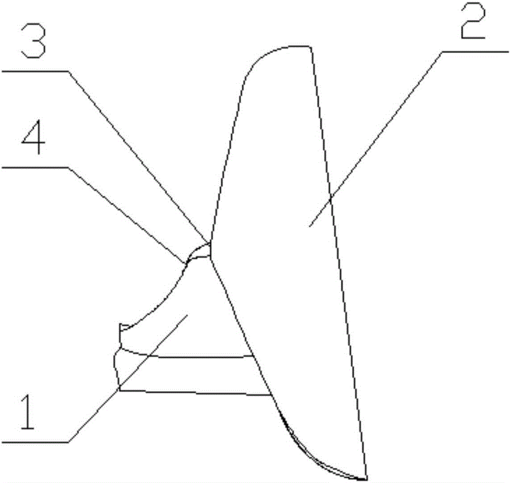
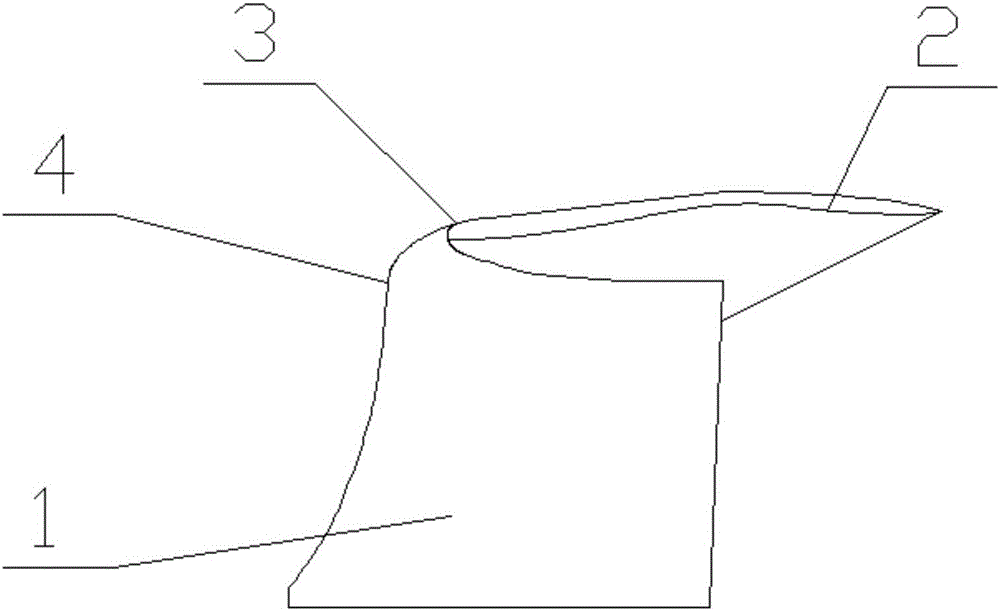
[0028] Such as Figure 1-3 As shown, a T-shaped tail includes a vertical tail 1 and a horizontal tail 2, and the joints of the vertical tail 1 and the horizontal tail 2 are arranged alternately. The specific distribution of the junction of the vertical tail 1 and the horizontal tail 2 is as follows: the front end 3 of the horizontal tail 2 is arranged behind the front edge 4 of the horizontal tail 2 . The height of the vertical tail 1 is D, the height of the fuselage 5 is h, the height difference between the vertical tail 1 and the fuselage 5 is D-h, D-h=1 / 2D. The height of the fuselage 5 is specifically: the height difference between the top of the fuselage 5 and the root of the vertical tail 1 .

[0029] An aircraft equipped with a T-shaped tail, the aircraft includes a fuselage 5, the tail of the fuselage 5 is provided with a T-shaped tail, the T-shaped tail includes a vertical tail 1 and a horizontal tail 2, and the horizontal tail 2 is symmetrical Airfoil, the root of t...

Embodiment 2

[0031] Such as Figure 1-3 As shown, a T-shaped tail includes a vertical tail 1 and a horizontal tail 2, and the joints of the vertical tail 1 and the horizontal tail 2 are arranged alternately. The specific distribution of the junction of the vertical tail 1 and the horizontal tail 2 is as follows: the front end 3 of the horizontal tail 2 is arranged behind the front edge 4 of the horizontal tail 2 . The height of the vertical tail 1 is D, the height of the fuselage 5 is h, the height difference between the vertical tail 1 and the fuselage 5 is D-h, D-h=2 / 3D. The height of the fuselage 5 is specifically: the height difference between the top of the fuselage 5 and the root of the vertical tail 1 .

[0032] An aircraft equipped with a T-shaped tail, the aircraft includes a fuselage 5, the tail of the fuselage 5 is provided with a T-shaped tail, the T-shaped tail includes a vertical tail 1 and a horizontal tail 2, and the horizontal tail 2 is symmetrical Airfoil, the root of t...


PUM


Abstract

The invention discloses a T-shaped empennage and an aircraft with the same and belongs to the field of aircrafts. The T-shaped empennage comprises a vertical empennage and a horizontal empennage. The joint of the vertical empennage and the horizontal empennage is arranged in a staggered mode. The front end of the horizontal empennage is arranged behind the front end of the vertical empennage. The rear end of the horizontal empennage protrudes behind the rear end of the vertical empennage. A smooth arc face transition is formed between the front end of the horizontal empennage and the front end of the top face of the vertical empennage. According to the T-shaped empennage and the aircraft with the same, the flow field interference resistance ability of the whole T-shaped empennage is improved greatly based on a traditional T-shaped empennage, the stability of the whole aircraft is improved, and a connection structure of the vertical empennage and the horizontal empennage is simplified.

Description

technical field [0001] The present invention generally relates to aviation technology, in particular to an aircraft, in particular to a T-shaped tail and an aircraft equipped with a T-shaped tail. Background technique [0002] T-shaped tail is a structural type of tail. According to the layout relationship between horizontal tail and vertical tail, other tail structures include: H-shaped layout, V-shaped tail layout, and multiple vertical tail layouts. The specific layout of the T-tail is: the horizontal tail is arranged on the vertical stabilizer of the aircraft. The advantage of the T-shaped tail layout is that the horizontal tail is less affected by the flow field of the fuselage, and is often used on transport aircraft with strong stability. Therefore, the aircraft introduced in this application mainly refers to transport aircraft. [0003] However, in the T-tail layout of traditional aircraft, the horizontal tail is still greatly affected by the flow field of the fusel...

Claims


Application Information

Patent Timeline
Patent Type & Authority Applications(China)
IPC IPC(8): B64C5/02B64C5/06B64C21/00
CPCB64C5/02B64C5/06B64C21/00
Inventor 李晓亮
Owner SF TECH
Learn More