Eureka AIR delivers breakthrough ideas for toughest innovation challenges, trusted by R&D personnel around the world.

Pipe lifting device

A technology for hanging pipes and booms, which is applied in the field of pipe hanging devices, which can solve the problems of easy accidents, low utilization rate, and reduced work efficiency of steel pipe transportation, etc., and achieve the effects of stable structure operation, improved work efficiency, and improved utilization rate

Inactive Publication Date: 2017-03-22
廊坊市管道人机械设备有限公司
View PDF0 Cites 6 Cited by
  • Summary
  • Abstract
  • Description
  • Claims
  • Application Information

AI Technical Summary

Problems solved by technology

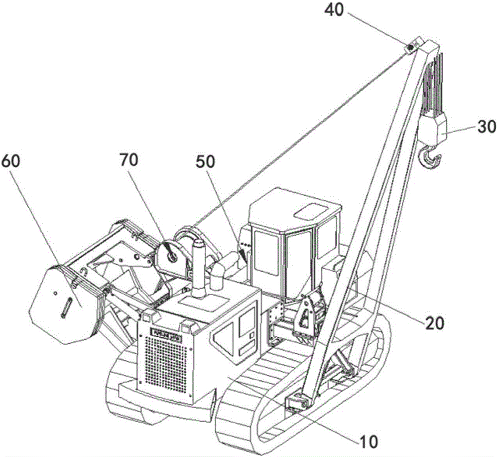
The jib assembly 20 adopts this side-mounted structure. Although it can meet the construction requirements on site and enable the jib of the jib assembly 20 to lift steel pipes with variable amplitude, there are still technical defects, specifically: due to the The frame assembly 20 is hinged on the bracket on the fixed frame, so the 360° rotation operation cannot be realized during the steel pipe lifting process, which reduces the working efficiency of the steel pipe transportation, hoisting, ditching and other processes
[0003] Although the excavator in the construction site has a slewing function, according to the construction specifications of the excavator, the excavator cannot be directly used to lift steel pipes (mainly because the strength of the excavator boom and the luffing method are not suitable for lifting steel pipes). It is prone to accidents, therefore, the use of excavators to hoist steel pipes is prohibited in the construction specifications of excavators
Therefore, although there are many equipments on the construction site, there is a problem that the utilization rate is not high.

Method used


Image

  • Pipe lifting device
  • Pipe lifting device
  • Pipe lifting device

Examples


Embodiment 1

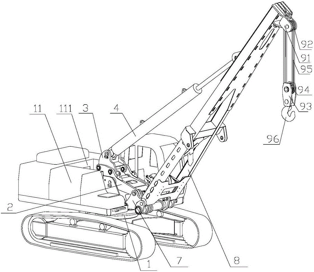
[0062] continue to combine figure 2 and Figure 5 , the luffing mechanism includes the luffing oil cylinder base 3 and the luffing oil cylinder 4, and the bottom end of the cylinder barrel of the luffing oil cylinder is provided with a circular through hole (not shown in the figure due to occlusion); the luffing oil cylinder base 3 includes two parallel The second side plate 31 is arranged and connected to each other, the luffing cylinder seat 3 is arranged between the two first side plates 21, and the second side plate 31 is attached to the first side plate 21, and the two second side plates 31 are respectively provided with two first through holes 32 opposite to the first mounting hole 22, and one is used for a second through hole 33 opposite to the circular through hole, and the first mounting hole 22 and the first through hole 32 pass through A pin is provided to connect the platform frame 2 and the luffing cylinder seat 3; a pin is provided in the circular through hole ...

Embodiment 2

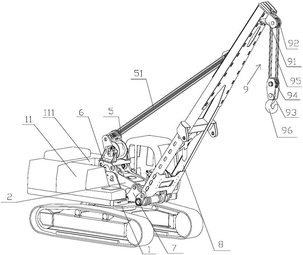
[0065] continue to combine image 3 , Figure 6 and Figure 7 , the luffing mechanism includes a luffing winch seat 6 and a luffing winch 5, and the luffing winch seat 6 includes a top plate 61 for installing the luffing winch 5 and two first clamping plates 62 respectively connected to the bottom sides of the top plate 61, The two first side plates 21 of the platform frame 2 are correspondingly inserted in the first clamping plate 62, the two first clamping plates 62 are provided with a third through hole 63 that can be opposite to the first mounting hole 22, the first mounting hole 22 and A pin shaft is passed through the third through hole 63 to detachably connect the luffing winch seat 6 to the platform frame 2 . The luffing winch 5 is a purchased part, on which a first wire rope 51 connected to the boom 8 is arranged, and the first wire rope 51 can drive the boom 8 to realize luffing under the action of the luffing cylinder 4 .

[0066] It can be seen from Embodiment 1...


PUM


Abstract

The invention discloses a pipe lifting device. The pipe lifting device comprises an excavator chassis, a lifting arm frame and a platform frame, wherein a platform is arranged on the excavator chassis, and is provided with a mounting groove; front mounting holes are oppositely formed in the front ends of two opposite side walls of the mounting groove, and back mounting holes are oppositely formed in the back ends of the two opposite side walls of the mounting groove; the lifting arm frame is detachably connected to the platform through the front mounting holes, and is hinged with a lifting arm; a pipe lifting module is arranged at the top end of the lifting arm; the platform frame is detachably connected to the platform through the back mounting holes, and is provided with a luffing mechanism for driving the lifting arm to perform luffing; and the platform frame is connected with the lifting arm frame. The lifting arm frame and the platform frame use existing mounting holes in the platform for forming stable triangular connection with the platform, so that the overall structure is more stable in operation, can rotate with loads by 360 degrees, realizes multiple purposes on one machine, increases the equipment utilization rate, and improves the pipe lifting efficiency.

Description

technical field [0001] The invention belongs to the technical field of oil and natural gas pipeline hoisting machinery, in particular to a pipe hanging device. Background technique [0002] In the construction of oil and gas pipelines, the transportation, hoisting and ditching of steel pipes are mainly completed by pipelayers. Pipelayers are important construction equipment in oil and gas pipeline construction, such as figure 1 As shown, the pipelayer is mainly composed of a chassis 10, a jib assembly 20, a lifting pulley block 30, a luffing pulley block 40, a hydraulic system 50, a counterweight mechanism 60, a lifting and luffing winch 70, and a hook, among which The two sides of the chassis 10 are respectively provided with a crawler belt, and a bracket extending outward is arranged on the fixed bracket for installing the crawler belt. A counterweight mechanism is required. The jib assembly 20 adopts this side-mounted structure. Although it can meet the construction req...

Claims


Application Information

Patent Timeline
Patent Type & Authority Applications(China)
IPC IPC(8): B66C23/36B66C23/64B66C23/62
Inventor 蔡革新王国锋徐瑞轩彭月显
Owner 廊坊市管道人机械设备有限公司
Why Eureka
Eureka Blog
Learn More