Rare earth oxide extraction equipment for rare earth waste recycling

A technology of rare earth oxides and rare earth wastes, applied in solvent extraction, process efficiency improvement, chemical instruments and methods, etc., can solve problems such as slow extraction speed, poor control of solution ratio, poor extraction effect, etc.

Inactive Publication Date: 2017-03-22
充梦霞
View PDF4 Cites 6 Cited by
  • Summary
  • Abstract
  • Description
  • Claims
  • Application Information

AI Technical Summary

Problems solved by technology

[0006] In order to overcome the disadvantages of poor extraction effect, slow extraction speed, and poor control of the ratio between the solutions when distributing two solutions with different coefficients, the technical problem to be solved by the present invention is to provide an extraction effect Rare earth oxide extraction equipment for rare earth waste recycling with good, fast extraction speed, and accurate observation of the ratio of the two solutions during deployment

Method used


Image

  • Rare earth oxide extraction equipment for rare earth waste recycling
  • Rare earth oxide extraction equipment for rare earth waste recycling
  • Rare earth oxide extraction equipment for rare earth waste recycling

Examples


Embodiment 1

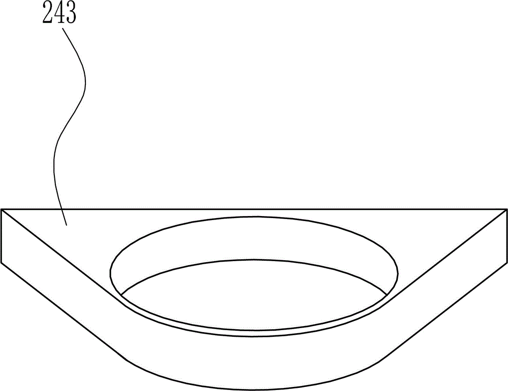
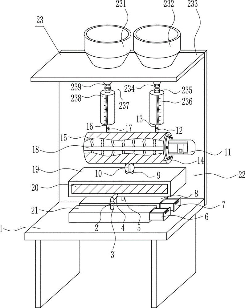
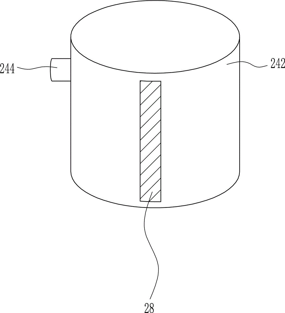
[0038] A kind of rare earth oxide extraction equipment for rare earth waste recycling, such as Figure 1-7 As shown, it includes a placement table 1, a first valve 2, a first liquid outlet pipe 3, a second liquid outlet pipe 4, a third liquid outlet pipe 5, a first storage box 6, a second storage box 7, a first storage box Box 8, fourth liquid outlet pipe 9, second valve 10, motor 11, third valve 12, first liquid inlet pipe 13, mixing cylinder 14, stirring blade 15, second liquid inlet pipe 16, fourth valve 17, Rotating shaft 18, static case 19, first transparent glass 20, second storage box 21 and rear side plate 22, the rear side of placing table 1 is welded with rear side plate 22, and the front side lower part of rear side plate 22 is connected by bolts A mixing cylinder 14 and a static tank 19 are connected, the static tank 19 is located at the bottom of the mixing cylinder 14, a second liquid inlet pipe 16 is welded on the left side of the top of the mixing cylinder 14, ...

Embodiment 2

[0040] A kind of rare earth oxide extraction equipment for rare earth waste recycling, such as Figure 1-7 As shown, it includes a placement table 1, a first valve 2, a first liquid outlet pipe 3, a second liquid outlet pipe 4, a third liquid outlet pipe 5, a first storage box 6, a second storage box 7, a first storage box Box 8, fourth liquid outlet pipe 9, second valve 10, motor 11, third valve 12, first liquid inlet pipe 13, mixing cylinder 14, stirring blade 15, second liquid inlet pipe 16, fourth valve 17, Rotating shaft 18, static case 19, first transparent glass 20, second storage box 21 and rear side plate 22, the rear side of placing table 1 is welded with rear side plate 22, and the front side lower part of rear side plate 22 is connected by bolts A mixing cylinder 14 and a static tank 19 are connected, the static tank 19 is located at the bottom of the mixing cylinder 14, a second liquid inlet pipe 16 is welded on the left side of the top of the mixing cylinder 14, ...


PUM


Abstract

The invention relates to rare earth oxide extraction equipment, in particular to rare earth oxide extraction equipment for rare earth waste recycling. In order to achieve the technical aims, the rare earth oxide extraction equipment for rare earth waste recycling is good in extraction effect, high in extraction speed and capable of precisely observing the ratio of two solutions during mixing. To achieve the above technical aims, the rare earth oxide extraction equipment for rare earth waste recycling comprises a containing table, a first valve, a first liquid outlet pipe, a second liquid outlet pipe, a third liquid outlet pipe, a first storage box, a second storage box, a first storage tank, a fourth liquid outlet pipe and the like. A rear side plate is welded to the rear side face of the containing table. According to the rare earth oxide extraction equipment for rare earth waste recycling, the quantity of the mother solution and the quantity of the extraction solution can be precisely controlled through a first material metering pipe and a second material metering pipe.

Description

technical field [0001] The invention relates to a rare earth oxide extraction device, in particular to a rare earth oxide extraction device for recycling rare earth waste. Background technique [0002] Rare earths are known as "industrial vitamins". Now it has become an extremely important strategic resource. Rare earth element oxides refer to oxides of 15 lanthanide elements with atomic numbers from 57 to 71 in the periodic table of elements, and oxides of scandium (Sc) and yttrium (Y), which are chemically similar to lanthanide elements, a total of 17 elements . Rare earth elements have been widely used in petroleum, chemical industry, metallurgy, textile, ceramics, glass, permanent magnet materials and other fields. [0003] Extraction, also known as solvent extraction or liquid-liquid extraction, also known as extraction, is a unit operation that uses the different solubility of the components in the system to separate the mixture. That is, it is a method of transfer...

Claims


Application Information

Patent Timeline
IPC IPC(8): C22B3/02C22B3/26C22B7/00C22B59/00
CPCB01D11/0257C22B3/02C22B7/006C22B59/00C22B3/26Y02P10/20
Inventor 不公告发明人
Owner 充梦霞
Why Eureka
Try Eureka