Swinging type shock insulation layer capable of achieving overall sliding friction of bottom surface

A sliding friction, seismic isolation layer technology, applied in earthquake-proof, protective buildings/shelters, building components, etc., can solve the problem that the isolation bearing is difficult to meet the super-seismic performance of the isolation building, and achieve easier reset, Overall good effect

Active Publication Date: 2017-03-22
HARBIN INST OF TECH
View PDF4 Cites 4 Cited by
  • Summary
  • Abstract
  • Description
  • Claims
  • Application Information

AI Technical Summary

Problems solved by technology

[0003] In order to solve the problem that the existing seismic isolation bearings are difficult to meet the anti-ultra-large earthquake performance of hig

Method used


Image

  • Swinging type shock insulation layer capable of achieving overall sliding friction of bottom surface
  • Swinging type shock insulation layer capable of achieving overall sliding friction of bottom surface
  • Swinging type shock insulation layer capable of achieving overall sliding friction of bottom surface

Examples


Example Embodiment

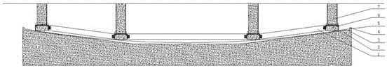
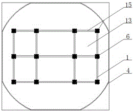
[0025] Specific implementation mode one: as Figure 1-2 As shown, the bottom integral sliding friction pendulum shock-isolation layer of this embodiment consists of a bottom spherical shell 3 and an upper spherical frame 15, wherein:

[0026] The lower side of the bottom spherical shell 3 is integrated with the concrete foundation or the lower structure 1, and the upper surface is an arc-shaped spherical surface 13 with a large span and a large curvature radius;

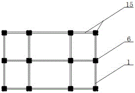
[0027] The upper spherical frame 15 is connected by several sliders 5, connecting beams 1, load-bearing columns 7, and connecting members 6. The lower part of the connecting members 6 is welded with the sliders 5, and the side of the connecting members 6 is connected with the connecting beams 1. The connecting members 6. The upper part is connected to the upper structure through the load-bearing column 7, and the upper structure is connected to the shock-isolation layer by means of the load-bearing column 7. The slid...

Example Embodiment

[0029] Specific implementation mode two: as Figure 3-7 As shown, in this embodiment, the cross section of the connecting member 6 is box-shaped, the interior is filled with concrete and embedded with bolts 9, the lower cover plate of the connecting member 6 is welded to the top of the slider 5, and the side of the connecting member 6 passes through the beam end angle steel plate The 8 bolt connection is mixed with the welding at the flange and the bolt welding of the I-shaped connecting beam 1 to form the upper spherical frame 15 as a whole.

[0030] The upper part of the connecting member 6 is provided with a circular or rectangular steel sleeve 17, and concrete is poured into the steel sleeve 17 to form a load-bearing column 7 connected to the upper structure; the upper surface cover plate of the connecting member 6 is welded to the combined column cover plate 16 on the bottom surface of the steel sleeve 17 , The outer side of the steel sleeve 17 is provided with a column l...

Example Embodiment

[0032] Specific implementation mode three: as figure 1 , 2 , 7, in this embodiment, the span of the bottom spherical shell 3 is greater than that of the upper spherical frame 15, and the height of the edge is close to or reaches the ground surface, and a limit ring 4 is arranged on the edge of the arc-shaped spherical surface 13, and at the end of the arc-shaped spherical surface 13 A wind-resistant ring 11 is provided outside the balance position of the outer slide block 5 .


PUM


Abstract

The invention discloses a swinging type shock insulation layer capable of achieving overall sliding friction of the bottom surface. The shock insulation layer comprises a bottom surface spherical shell and an upper-portion spherical-surface framework, wherein the lower side of the bottom surface spherical shell and a concrete foundation or a lower structure are cast integrally, and the upper surface is a large-span large-curvature-radius arc spherical surface; the upper-portion spherical-surface framework is formed by connecting a plurality of sliding blocks, connecting beams, load bearing pillars and connecting components, the lower portions of the connecting components are welded to the sliding blocks, the sides of the connecting components are connected with the connecting beams, the upper portions of the connecting components are connected with an upper structure through the load bearing pillars, the sliding blocks are in lap-joint with the upper surface of the bottom surface spherical shell, the lower surfaces of the sliding blocks keep consistent with corresponding positions of the arc spherical surface, and point-contact is avoided. The sliding spherical-surface framework is formed through connection between the sliding blocks and forms the swinging type shock insulation layer capable of achieving overall sliding friction of the bottom surface together with the bottom surface spherical shell. The bottom surface spherical shell has a large span, the allowed deformation in the horizontal direction is far higher than that of a shock insulation support, and the horizontal deformation of the shock insulation layer under super-large shock can be completely met.

Description

technical field [0001] The invention belongs to the technical field of shock absorption and isolation of building structures, and relates to a bottom integral sliding friction pendulum type shock isolation layer. Background technique [0002] Seismic isolation technology is an outstanding research achievement in the field of structural seismicity in the past 50 years, and has been widely used in my country. Seismic isolation measures can make the superstructure in an elastic or weakly nonlinear state under the action of a large earthquake, reducing the seismic response of the superstructure. However, due to its clear failure mode, the deformation of the isolation layer and the overturning of the overall structure are prominent problems of the isolation structure under the action of a super large earthquake. Common seismic isolation devices for building structures include rubber bearings and friction pendulum bearings, whose horizontal deformation capacity is limited by the ...

Claims


Application Information

Patent Timeline
IPC IPC(8): E04B1/98E04H9/02
CPCE04H9/021
Inventor 欧进萍武沛松关新春
Owner HARBIN INST OF TECH
Why Eureka
Try Eureka