Steel platform formwork lifting point bearing beams and lifting method for formwork system

A hoisting method and technology of steel platform, applied in formwork/template/work frame, processing of building materials, preparation of building components on site, etc. Convenience, simple structure, simple and quick operation

Active Publication Date: 2017-03-22
SHANGHAI CONSTRUCTION GROUP
View PDF6 Cites 4 Cited by
  • Summary
  • Abstract
  • Description
  • Claims
  • Application Information

AI Technical Summary

Problems solved by technology

[0005] For the existing steel platform formwork system, fixed lifting points are used when lifting the formwork. With the shrinkage of the wall, the inclination angle between the fixed lifting point and the formwork lifting point becomes larger and larger, which seriously affects the rapid installation of the formwork. And there is a problem of potential safety hazards. The present invention provides a simple structure, convenient operation, fast and effective hoisting method for the load-bearing beam of the formwork lifting point of the steel platform and the formwork system, so as to reduce the vertical displacement difference of the formwork and realize the improvement of the existing Steel platform for optimization and improvement

Method used


Image

  • Steel platform formwork lifting point bearing beams and lifting method for formwork system
  • Steel platform formwork lifting point bearing beams and lifting method for formwork system
  • Steel platform formwork lifting point bearing beams and lifting method for formwork system

Examples


Embodiment 1

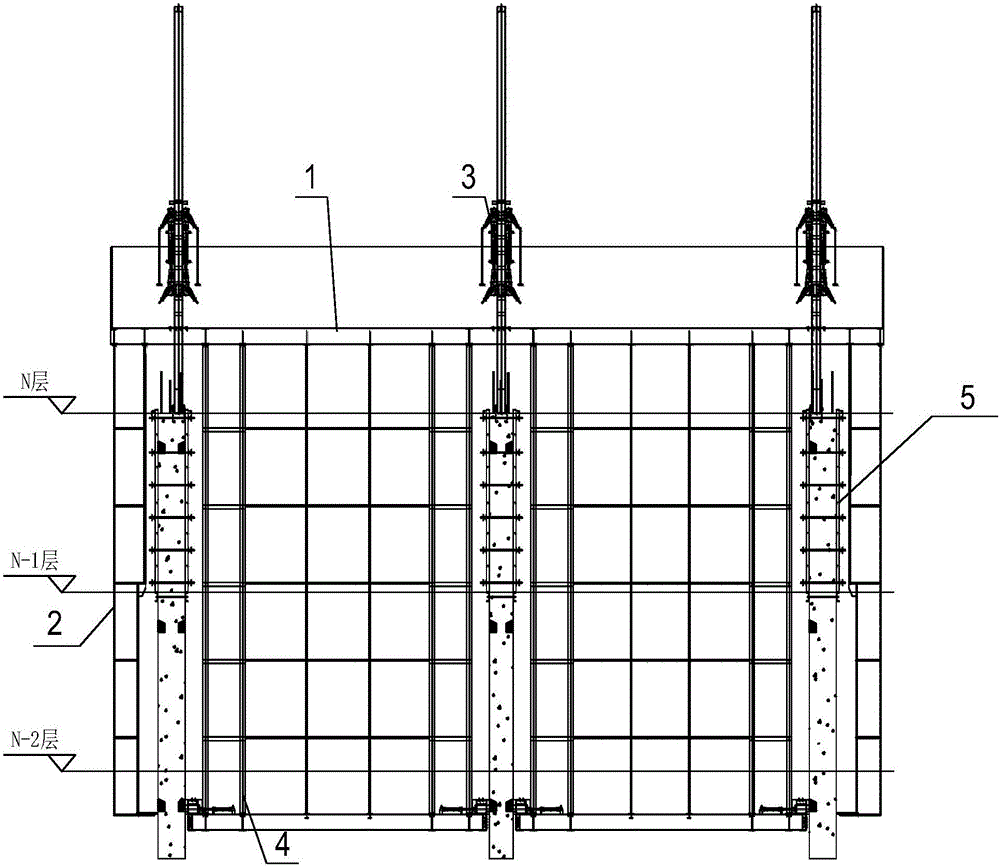
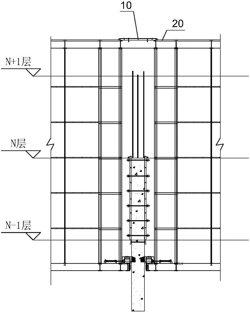
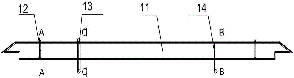
[0037] see Figure 2 to Figure 6 , the hydraulic climbing integral steel platform formwork system is fixed on the vertical concrete structure of the core tube, and the load-bearing beam 1 of the formwork lifting point is arranged across the top of the formwork of the core wall wall so that it is perpendicular to the horizontal direction of the shear wall, that is, the formwork hanging The point load-bearing beam 1 is set across the steel platform, located above the shear wall of the core tube, and spans the opening of the steel platform. The formwork hanging point load-bearing beam 10 includes: the main beam 11, which is embedded in the steel platform decking The upper surface of 20; the handle ring 12, the handle ring 12 is arranged at the two ends of the main beam 11; at least one movable ring 13, the movable ring 13 surrounds the main beam 11, and can follow the closing of the wall along the The main girder 11 slides and is located on the shrinking side of the wall of the c...


PUM


Abstract

The invention provides steel platform formwork lifting point bearing beams and a lifting method for a formwork system, and belongs to the technical field of building construction. The steel platform formwork lifting point bearing beams and the lifting method for the formwork system are used for solving the problems that formwork rapid installation is seriously affected and potential safety hazards exist due to the fact that fixed lifting points are adopted during formwork lifting in existing steel platform formwork systems. Each formwork lifting point bearing beam comprises a main beam embedded in a steel platform floor plate, hand pull rings arranged at the two ends of the main beam and at least one movable lifting ring. The movable lifting rings surround the main beams, can slide along the main beams and are located on the folding-unfolding side of a wall. The lifting method for the formwork system comprises the steps that 1, the multiple steel platform formwork lifting point bearing beams are installed on the steel platform floor plate; 2, after construction of a first construction section is finished, the steel platform formwork system is jacked to a second construction section and fixed; and 3, after construction of the second construction section is finished, a chain block is installed on the lifting rings of the bearing beams, the formwork system is lifted to a third construction section, and operation is circulated and repeated till lifting of the whole formwork system is completed.

Description

technical field [0001] The invention relates to the technical field of building construction, in particular to a formwork lifting point load-bearing beam of a steel platform and a formwork system hoisting method. Background technique [0002] In recent years, super high-rise buildings have developed rapidly in my country. The construction of super high-rise buildings mostly adopts the construction of horizontal structure and vertical structure separately, and the vertical structure is ahead of the horizontal structure construction. Therefore, the construction of super high-rise shear walls has higher requirements for verticality. In the case of high altitude without horizontal structural support, higher requirements are put forward for the verticality of the shear wall formwork. [0003] For domestic super high-rise buildings, the hydraulic climbing integral steel platform formwork system is usually used. Such as figure 1 As shown, the steel platform formwork system usually...

Claims


Application Information

Patent Timeline
IPC IPC(8): E04G11/28E04G21/00
CPCE04G11/28E04G21/00
Inventor 龚剑扶新立张秀凤马静秦鹏飞
Owner SHANGHAI CONSTRUCTION GROUP
Why Eureka
Try Eureka