Split-type spiral drilling machine

A kind of auger drilling rig, split type technology, applied in the direction of drill bits, drilling equipment, earthwork drilling and mining, etc., can solve the problems of low drilling efficiency, no open horizontal auger drilling rig, and inconvenient movement, so as to avoid pipeline laying and facilitate lifting and moving Sexuality, the effect of simplifying the organization

Inactive Publication Date: 2017-03-22
广西固瑞科技股份有限公司
View PDF9 Cites 1 Cited by
  • Summary
  • Abstract
  • Description
  • Claims
  • Application Information

AI Technical Summary

Problems solved by technology

However, the horizontal auger drilling machine has not been disclosed. The existing horizontal auger drilling machine has low drilling efficiency and is inconvenient to move.

Method used


Image

  • Split-type spiral drilling machine
  • Split-type spiral drilling machine
  • Split-type spiral drilling machine

Examples


Embodiment Construction

[0020] The principles and features of the present invention are described below in conjunction with the accompanying drawings, and the examples given are only used to explain the present invention, and are not intended to limit the scope of the present invention.

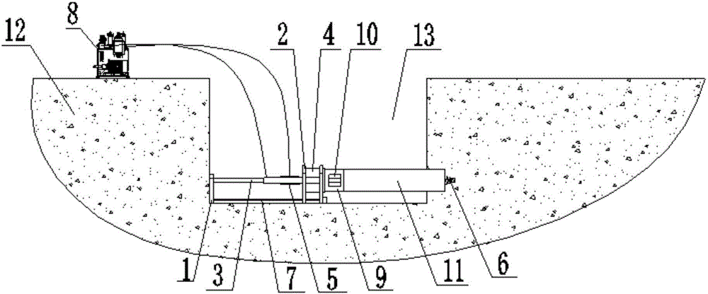
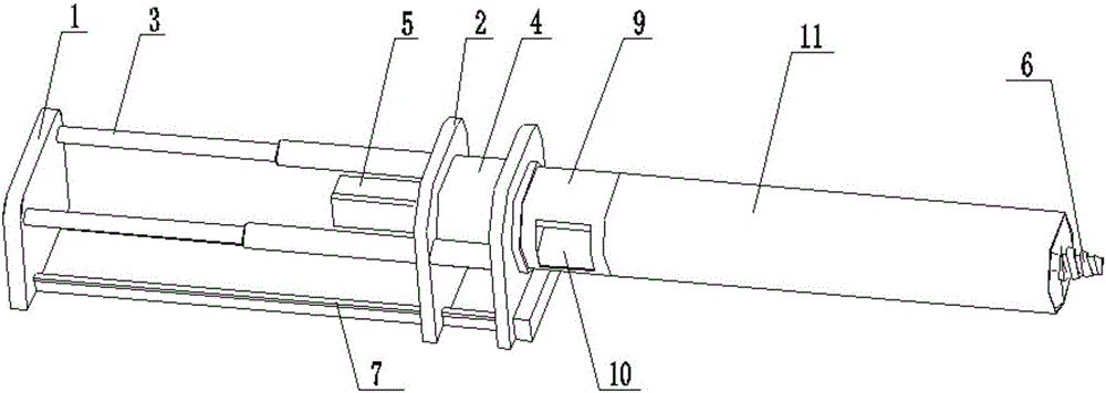
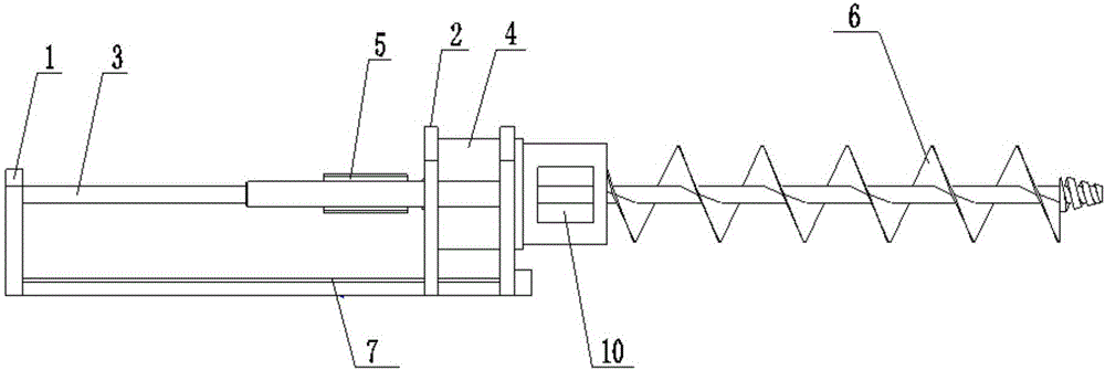
[0021] Such as Figure 1 to Figure 3 As shown, a split type auger drill includes a frame 1, a support frame 2, an oil cylinder 3, a reduction gear 4, a hydraulic motor 5 and an auger bit 6; the bottom of the frame 1 is provided with a guide rail 7, and the support frame 2 moveably placed on the guide rail 7; two oil cylinders 3 are provided, the output shafts of the two oil cylinders 3 are fixedly connected with the frame 1, and the two oil cylinders 3 are far away from their output shafts One end of each is fixedly connected with the support frame 2, and the output shafts of the two oil cylinders 3 expand and contract to drive the support frame 2 to move on the guide rail 7; the speed reduction device 4 is placed o...


PUM


Abstract

The invention relates to a split-type spiral drilling machine which comprises a rack, a supporting frame, an oil cylinder, a speed reduction device, a hydraulic motor and a spiral drill bit, wherein a guide rail is disposed on the bottom of the rack, and the supporting frame is movably disposed on the guide rail; an output shaft of the oil cylinder is firmly connected to the rack, one end of the oil cylinder remote from the output shaft is firmly connected to the supporting frame, and the output shaft of the oil cylinder stretches and contracts to drive the supporting frame to move on the guide rail; the speed reduction device is disposed on the supporting frame; and the hydraulic motor is placed on one side of the speed reduction device close to the oil cylinder, an output shaft of the hydraulic motor is connected to an input end of the speed reduction device, an output end of the speed reduction device is connected to the spiral drill bit, and the output shaft of the hydraulic motor drives rotation of the spiral drill bit via the speed reduction device so as to carry out drilling. In comparison with the prior art, the machine provided by the invention has the advantages that mechanism are simplified; construction requirements are reduced; drilling stability and drilling efficiency are increased; and motion convenience is enhanced.

Description

technical field [0001] The invention relates to the technical field of drilling rigs, in particular to a split type auger drilling rig. Background technique [0002] Application number: 200610036047.9 The invention discloses a pipe jacking construction method in which a horizontal auger drilling machine and a horizontal directional drilling machine work together. The method first uses a horizontal drilling machine to drill a pilot hole along the design track of the pipeline to be laid on the side of the receiving well to the pipe jacking In the working well, the drill pipe of the horizontal directional drilling machine is connected with the drill bit and auger pipe of the horizontal auger drilling machine in the working well. The design trajectory of the pipeline to be laid in the hole is advanced, and the pipeline laying that requires precise elevation control is finally completed. But the horizontal auger drilling machine is not disclosed, and the existing horizontal auge...

Claims


Application Information

Patent Timeline
IPC IPC(8): E21B7/00E21B10/42E21B4/02
CPCE21B7/00E21B4/02E21B10/42
Inventor 黄成博潘文飞周旭明
Owner 广西固瑞科技股份有限公司
Why Eureka
Try Eureka