Automatic limiting and looseness-resisting fastening assembly

A fastening component and automatic limit technology, which is applied in the direction of threaded fasteners, locking fasteners, connecting components, etc., can solve the problem of difficult fastening parts management, connecting bolts without limit, bolts, spring washers, flat washers Problems such as falling off, to achieve the effect of improving efficiency, easy management, and protecting equipment from collisions

Active Publication Date: 2017-03-22
东方蓝天钛金科技有限公司
View PDF7 Cites 4 Cited by
  • Summary
  • Abstract
  • Description
  • Claims
  • Application Information

AI Technical Summary

Problems solved by technology

[0003] There are many deficiencies in this connection technology: (1) Since the bolts, spring washers, and flat washers are a single part and separated from the equipment, when the equipment is connected to the body structure, it needs two people to cooperate to complete, and it is easy to cause bolts during installation and disassembly. , Spring washers and flat washers fall off, making it difficult to manage the fastening parts; (2) During the connection process between the equipment and the body structure, the connecting bolts cannot be positioned in the equipment mounting holes, and the efficiency of connecting the external thread of the bolt with the internal thread of the structure is low
(3) Unlimited function of connecting bolts
When the bolts are disassembled, the separation of the equipment and the body structure cannot be judged visually and intuitively, which is extremely inconvenient to use

Method used


Image

  • Automatic limiting and looseness-resisting fastening assembly
  • Automatic limiting and looseness-resisting fastening assembly
  • Automatic limiting and looseness-resisting fastening assembly

Examples


Embodiment 1

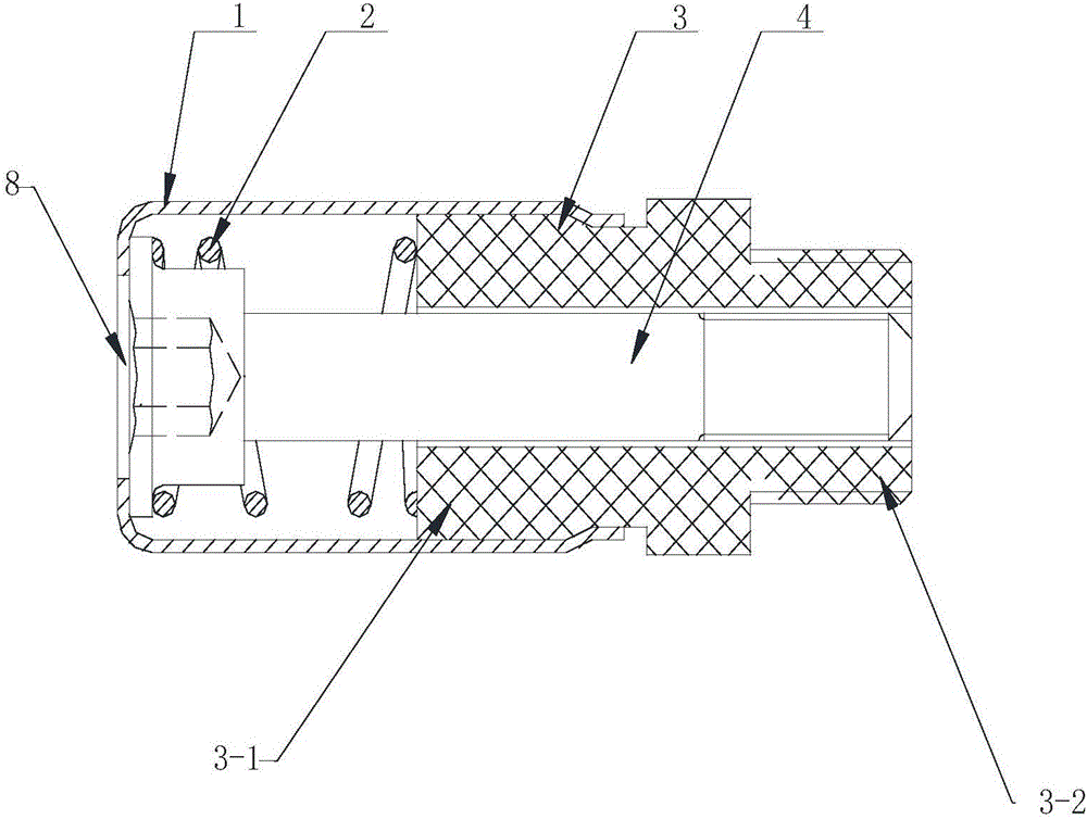
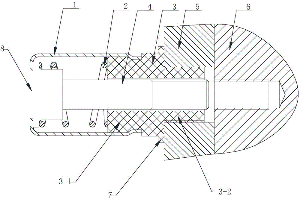
[0026] Such as Figure 1~3 As shown, it includes a limit sleeve 1, a positioning sleeve 3 and a bolt 4. The front portion of the limit sleeve 1 is open, and the rear portion is provided with a screwdriver jack 8. The positioning sleeve 3 is a hollow cylindrical structure, and the positioning sleeve 3 The front end is provided with a small-diameter insertion end 3-2, and the rear end is fixedly connected with the front part of the limit sleeve 1, forming a limit cavity in the limit sleeve 1, and the threaded end of the bolt 4 is inserted into the Installed in the positioning sleeve 3, the nut end is located in the limiting cavity, a spring 2 is arranged between the nut and the positioning sleeve 3; the diameter of the screwdriver hole 8 is smaller than that of the nut diameter of.

[0027] The rear end of the positioning sleeve 3 is provided with a connected step 3-1, and the positioning sleeve 1 is assembled on the step 3-1 of the positioning sleeve through a rolling process;...

Embodiment 2

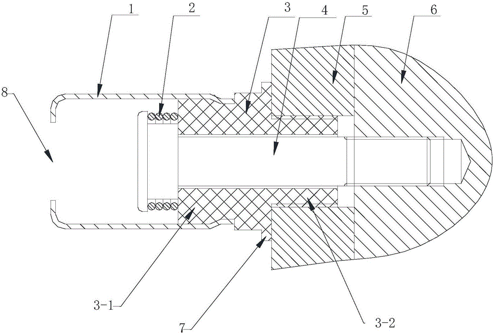
[0034] Such as Figure 4 As shown, it includes a limiting sleeve 1, a positioning sleeve 3 and a bolt 4 in an integrated structure. The positioning sleeve 3 is a hollow cylindrical structure. The front end of the positioning sleeve 3 is provided with a small-diameter insertion end 3-2, and the rear end It is integrally connected with the front part of the limit sleeve 1, and a limit cavity is formed in the limit sleeve 1. The rear part of the limit sleeve 1 is provided with a screwdriver socket, and the threaded end of the bolt is inserted into the In the positioning sleeve 3, the nut end is located in the limiting cavity, and a spring 2 is arranged between the nut and the positioning sleeve 3; the diameter of the screwdriver hole is smaller than the diameter of the nut .


PUM


Abstract

The invention relates to an automatic limiting and looseness-resisting fastening assembly and belongs to the technical field of fastening connection. The automatic limiting and looseness-resisting fastening assembly comprises a limiting sleeve, a locating sleeve and a bolt. The front portion of the limiting sleeve is provided with an opening, and the back portion of the limiting sleeve is provided with a screwdriver insertion hole. The locating sleeve is of a hollow cylinder structure. The front end of the locating sleeve is provided with a small-diameter insertion end. The back end of the locating sleeve is fixedly connected with the front portion of the limiting sleeve. A limiting cavity is formed in the limiting sleeve. The threaded end of the bolt is inserted into the locating sleeve. The nut end of the bolt is located in the limiting cavity. A spring is arranged between the nut and the locating sleeve. The diameter of the screwdriver insertion hole is smaller than that of the nut. The automatic limiting and looseness-resisting fastening assembly has the beneficial effects that the bolt is not prone to disengagement in the mounting and dismounting process, the connected bolt can be positioned in an equipment installation hole, and the connection efficiency between external threads of the bolt and structure internal threads is improved; and when the bolt is dismounted, the bolt is jacked out by the spring through resilience force, tactile feedback is provided for an operator, so that the operator knows that dismounting is completed, and naked-eye observation is not needed.

Description

technical field [0001] The invention relates to an automatic position-limiting and anti-loosening fastening assembly, which belongs to the technical field of fastening connections. Background technique [0002] In many occasions such as aircraft, mobile monitoring, and laboratories, it is necessary to connect the monitoring equipment to the body structure. At the same time, in order to meet the regular maintenance and repair of the monitoring equipment, the connection between the equipment and the body structure is required to be detachable. The existing connection technology usually uses bolts, spring washers, and flat washers to fasten the equipment and the body structure. When installing, install the spring washer and flat washer on the bolt, then pass the bolt through the equipment installation hole, and turn the bolt clockwise to make the outer thread of the bolt and the inner thread of the hull structure screw together to complete the installation; when dismounting, tu...

Claims


Application Information

Patent Timeline
IPC IPC(8): F16B39/02F16B39/26
CPCF16B39/10F16B39/26
Inventor 申庆援王晓亮潘彦霖张志成孙凯
Owner 东方蓝天钛金科技有限公司
Why Eureka
Try Eureka