A micro-combustion chamber for micro-thermophotonics system

A micro-combustion chamber, micro-thermal photoelectric technology, applied in the direction of combustion, combustion type and combustion method using catalytic materials, can solve problems such as less research, and achieve enhanced space reaction, utilization rate, combustion efficiency and wall temperature. Effect

Inactive Publication Date: 2018-10-09
JIANGSU UNIV
View PDF4 Cites 0 Cited by
  • Summary
  • Abstract
  • Description
  • Claims
  • Application Information

AI Technical Summary

Problems solved by technology

[0006] At present, scholars at home and abroad have done some work on this problem. Some scholars have found that the use of porous media can relatively increase the temperature of the outer wall of the combustion chamber by filling the combustion chamber with porous media, mainly because the porous media can provide A more uniform temperature distribution is extremely effective for improving the efficiency of micro-thermal photoelectric systems. Scholars at home and abroad have also done some research on the structure of the combustion chamber. The research results show that changing the structure of the combustion chamber can make the flame more stable. More fully stable combustion in the combustion chamber, but there are relatively few researches on the combination of these two parts at home and abroad

Method used


Image

  • A micro-combustion chamber for micro-thermophotonics system
  • A micro-combustion chamber for micro-thermophotonics system

Examples


Embodiment Construction

[0025] The present invention will be further described below in conjunction with the accompanying drawings and specific embodiments, but the protection scope of the present invention is not limited thereto.

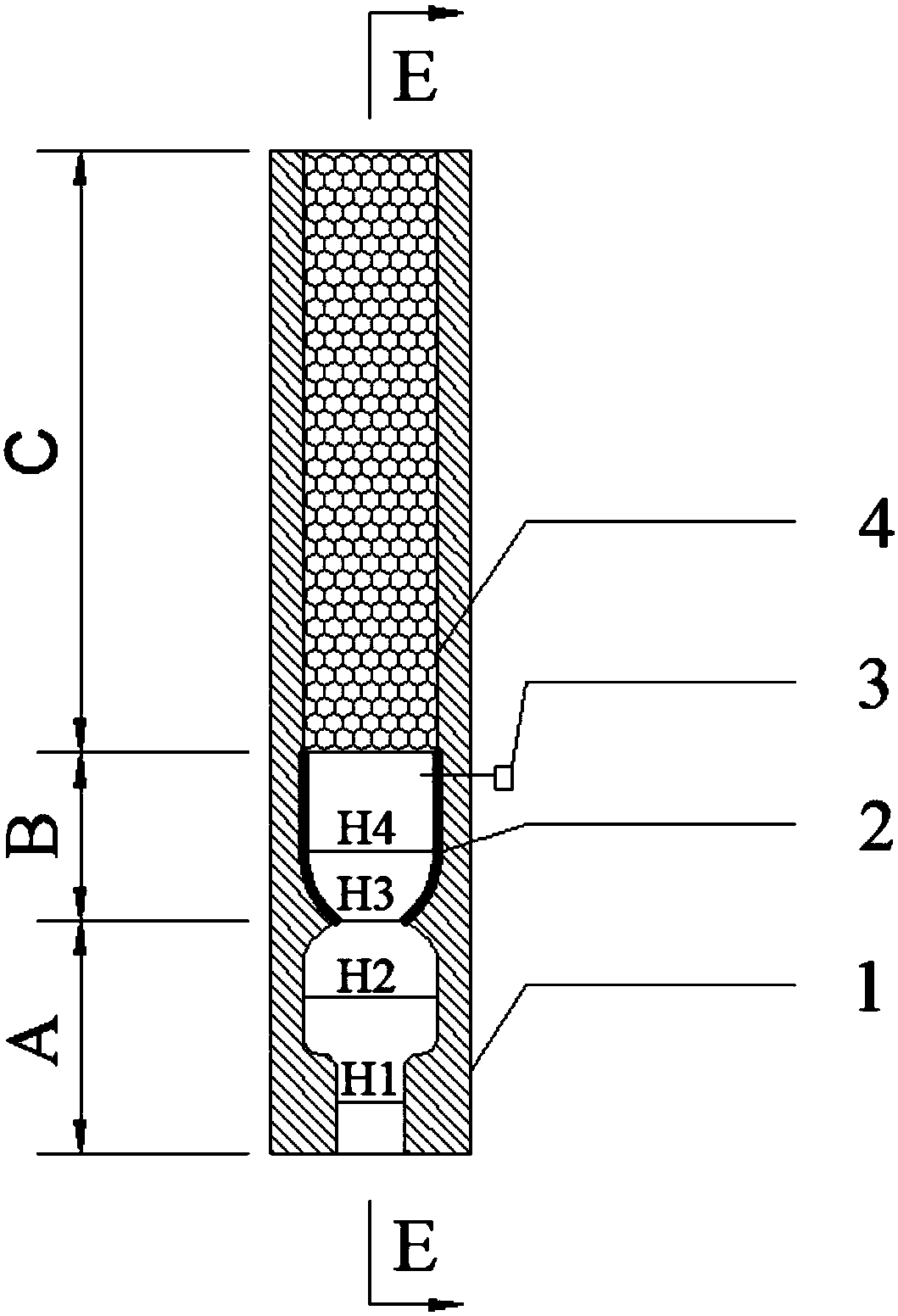
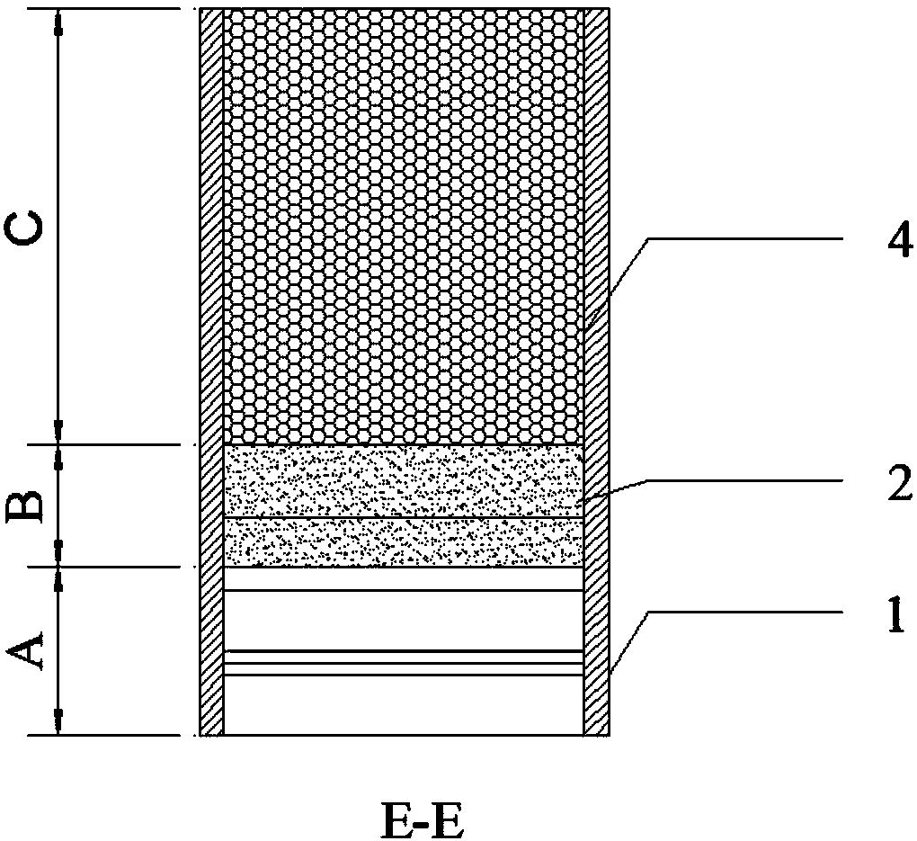
[0026] A micro-combustion chamber for a micro-thermophotoelectric system, comprising a combustion chamber wall 1 and an ignition needle 3; the combustion chamber wall 1 is sequentially composed of a stable combustion area A, a catalytic area B and a porous medium area C; the combustion chamber The thickness of the wall surface is 0.5mm-1mm; an ignition needle 3 is provided in the catalytic area B; a stable area and a pit area are provided in the stable combustion area A, and the cross-sectional area of ​​the stable area is set as S H1 , the cross-sectional area of ​​the pit area is set as S H2 , the plateau region transitions to the pit region through rounded corners, and S H1 H2 ; Inside the catalytic zone B is a variable cross-section area, and the cross-sectional area...


PUM


Abstract

The invention provides a micro combustor for a micro thermophotovoltaic system. The micro combustor comprises a combustor wall surface and an ignition needle. The combustor wall surface is sequentially composed of a stable combustion area, a catalytic area and a porous medium area. The ignition needle is arranged in the catalytic area. A steady region and a concave pit region are arranged in the stable combustion area. The sectional area of the steady region is set to be S<H1>, and the sectional area of the concave pit region is set to be S<H2>. The steady region is transited to the concave pit region through a circular corner, and S<H1> is smaller than S<H2>. The interior of the catalytic area is a variable cross-section area. The sectional area of the small end surface of the variable cross-section area is set to be S<H3>, the sectional area of the large end surface of the variable cross-section area is set to be S<H4>, and S<H3> is smaller than S<H2> and S<H4>. The catalytic area is internally soaked with catalytic agents. According to the micro combustor for the micro thermophotovoltaic system, by improving the spatial reaction of combustible gas in the micro combustor, fuel combustion is more sufficient, more heat is released, and the energy utilization rate is increased.

Description

technical field [0001] The invention relates to the technical field of micro-scale thermo-photoelectric energy conversion, in particular to a micro-combustion chamber for a micro-thermo-photoelectric system. Background technique [0002] In recent years, with the development of micro-nano science and technology, Micro Electro-Mechanical System (MEMS) characterized by extremely small shape and size or operation size has become a high-tech technology for people to understand the microscopic field and transform the objective world. It is also recognized as one of the research fields with the most development potential by the scientific and technological circles. Due to the disadvantages of low energy density and discontinuous energy supply, traditional batteries cannot be used as MEMS power sources. Under such a background, a micro-power system based on hydrocarbon fuel combustion came into being. The density is much higher than traditional batteries. [0003] Micro-thermal p...

Claims


Application Information

Patent Timeline
Patent Type & Authority Patents(China)
IPC IPC(8): F23C13/08F23C13/00
CPCF23C13/00F23C13/08F23C2900/13001
Inventor 潘剑锋卢志刚卢青波唐爱坤
Owner JIANGSU UNIV
Why Eureka
Try Eureka