
Improvement method of display panel machining technology and display panel machining equipment

A display panel and processing technology technology, applied in the improvement of display panel processing technology, display panel processing equipment field, can solve the problem of affecting UVMPad voltage application, lower board cannot be separated, etc., to improve production yield, ensure production and processing efficiency, The effect of eliminating static electricity

Inactive Publication Date: 2017-03-22
HKC CORP LTD +1
View PDF5 Cites 2 Cited by
  • Summary
  • Abstract
  • Description
  • Claims
  • Application Information

AI Technical Summary

Problems solved by technology

[0003] The purpose of the present invention is to provide a method for improving the display panel processing technology and display panel processing equipment, aiming to solve the problem of the inability to separate the lower plate due to static electricity when the residual material is taken from the SCU processing technology in the current technology, which affects the follow-up process UVM Pad voltage application The problem

Method used


Image

  • Improvement method of display panel machining technology and display panel machining equipment
  • Improvement method of display panel machining technology and display panel machining equipment
  • Improvement method of display panel machining technology and display panel machining equipment

Examples


Embodiment Construction

[0025] In order to make the object, technical solution and advantages of the present invention clearer, the present invention will be further described in detail below in conjunction with the accompanying drawings and embodiments. It should be understood that the specific embodiments described here are only used to explain the present invention, not to limit the present invention.

[0026] It should be noted that when an element is referred to as being “fixed” or “disposed on” another element, it may be directly on the other element or be indirectly on the other element. When an element is referred to as being "connected to" another element, it can be directly connected to the other element or indirectly connected to the other element.

[0027] It should also be noted that the orientation terms such as left, right, up, and down in this embodiment are only relative concepts or refer to the normal use state of the product, and should not be regarded as limiting.

[0028] explai...


PUM


Abstract

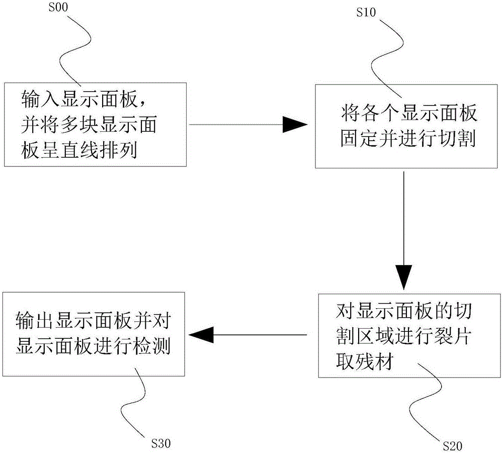
The invention provides an improvement method of a display panel machining technology and display panel machining equipment. The improvement method of the display panel machining technology comprises the following steps that 10, single board cutting machining cutting is performed on a unilateral glass panel of a liquid crystal panel; 20, shred residual materials are taken from a shred region of the cut glass panel and the liquid crystal panel, wherein an insulation spacer layer is additionally arranged between an array cushion layer and a cutting region of the cut glass panel; 30, the spacer layer is removed, and the array cushion layer is exposed, and then the liquid crystal panel is output. By applying the technical scheme, the problems of machining technologies in the prior art can be solved.

Description

technical field [0001] The invention relates to the technical field of liquid crystal equipment research, in particular to a method for improving a display panel processing technology and display panel processing equipment. Background technique [0002] In the current technology, the staff cuts the semi-finished product of the liquid crystal panel to expose the Array Pad (matrix metal layer). Driving the metal layer) to apply voltage, so as to complete the polymerization reaction process of liquid crystal molecules. However, in the current technology, since the upper and lower substrates in the liquid crystal panel are in contact with each other in a large area, and a large amount of static electricity is generated during cutting, this causes the lower substrate to fail to detach due to static electricity when removing residual materials, which affects the subsequent process UVM Pad voltage application, As a result, the processing yield of the liquid crystal panel is affect...

Claims


Application Information

Patent Timeline
Patent Type & Authority Applications(China)
IPC IPC(8): G02F1/1333G02F1/13C03B33/02
CPCC03B33/02G02F1/1303G02F1/1333C03B33/033G02F1/133351Y02P40/57G02F1/133308G02F1/1339G02F1/13458G02F1/133331G02F1/13398
Inventor 简重光
Owner HKC CORP LTD
Learn More