Power distribution cabinet provided with buffer strip

A technology of buffer strips and power distribution cabinets, which is applied in the substation/power distribution device casing, electrical components, substation/switch layout details, etc., which can solve the problem of damage to electrical components and equipment in power distribution cabinets, hard metal round holes, and reduce the use of cables Life and other issues, to achieve the effect of protecting electrical components, prolonging service life, and convenient heat dissipation

Inactive Publication Date: 2017-03-22
国网山东济南市长清区供电公司 +1
View PDF0 Cites 3 Cited by
  • Summary
  • Abstract
  • Description
  • Claims
  • Application Information

AI Technical Summary

Problems solved by technology

[0002] Existing power distribution cabinets are generally arranged as rectangular cabinets. The cabinet body includes a front cabinet surface. There is an opening on the front cabinet surface for operators to adjust the electrical components in the power distribution cabinet. The cabinet body also includes a cover body. It can be opened or closed on the opening, but in the process of opening or closing the cover, the cover will collide with the front cabinet,

Method used


Image

  • Power distribution cabinet provided with buffer strip
  • Power distribution cabinet provided with buffer strip
  • Power distribution cabinet provided with buffer strip

Examples


Embodiment Construction

[0018] The following will clearly and completely describe the technical solutions in the embodiments of the present invention with reference to the accompanying drawings in the embodiments of the present invention. Obviously, the described embodiments are only some, not all, embodiments of the present invention. Based on the embodiments of the present invention, all other embodiments obtained by persons of ordinary skill in the art without making creative efforts belong to the protection scope of the present invention.

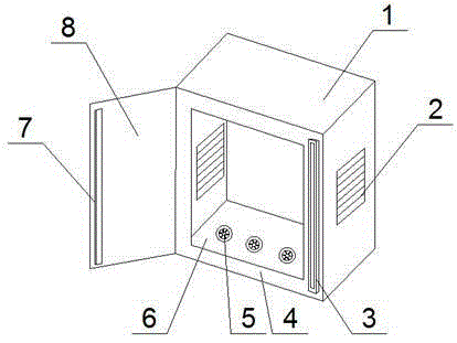
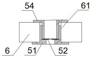
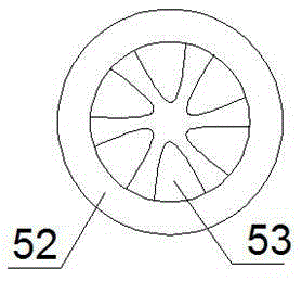
[0019] see Figure 1-4 , a power distribution cabinet with a buffer bar, including a cabinet body 1 and a cabinet door 8, both sides of the cabinet body 1 are provided with cooling ports 2, the front end of the cabinet body 1 is provided with a panel 4, and the panel 4 There is an opening, the left side of the panel 4 is hinged with a cabinet door 8, the right side of the panel 4 is provided with a buffer strip 3, the buffer strip 3 is vertically arranged and ...


PUM


Abstract

The invention discloses a power distribution cabinet provided with a buffer strip. The power distribution cabinet comprises a cabinet body and a cabinet door. The two sides of the cabinet body are respectively provided with a heat dissipation opening. The front end of the cabinet body is provided with a panel, which is provided with an opening. The left side of the panel is connected with the cabinet door in a hinged manner, and the right side of the panel is provided with the buffer strip. The buffer strip is arranged vertically, and the middle part of the buffer strip is provided with a buffer groove, and a magnet is disposed in the buffer strip. The cabinet door is provided with a protruding strip cooperated with the buffer groove, and the magnet is disposed in the protruding strip, and the magnetism of the magnet disposed in the protruding strip is the same as that of the magnet disposed in the buffer strip, and the direction of the magnet disposed in the protruding strip is opposite to the direction of the magnet disposed in the buffer strip. The bottom plate of the cabinet body is provided with a plurality of plastic rings, which comprise upper plastic rings and lower plastic rings. The upper plastic rings are in a threaded connection with the lower plastic rings in the installation holes in the bottom plate. The power distribution cabinet is advantageous in that the structural design is reasonable, use is convenient, and heat dissipation performance is good; function of buffering collision between the cabinet door and the panel is provided, and electric components in the cabinet body are protected; an external cable is clamped tightly without damaging the external layer of the cable, and the service lifetime of the cable is prolonged.

Description

technical field [0001] The invention relates to the technical field of a power distribution cabinet, in particular to a power distribution cabinet with a buffer strip. Background technique [0002] Existing power distribution cabinets are generally arranged as rectangular cabinets. The cabinet body includes a front cabinet surface. There is an opening on the front cabinet surface for operators to adjust the electrical components in the power distribution cabinet. The cabinet body also includes a cover body. It can be opened or closed on the opening, but in the process of opening or closing the cover, the cover will collide with the front cabinet surface, causing severe vibration and causing damage to the electrical components in the power distribution cabinet. [0003] The cables outside the power distribution cabinet usually enter the power distribution cabinet in strands from one to several round holes on the bottom plate of the cabinet. The metal round holes are hard, and...

Claims


Application Information

Patent Timeline
IPC IPC(8): H02B1/30H02B1/54H02B1/56
CPCH02B1/30H02B1/305H02B1/306H02B1/54H02B1/565
Inventor 韩伟郝付刚田华郝永华
Owner 国网山东济南市长清区供电公司
Why Eureka
Try Eureka