Access Control System

A monitoring system and access control technology, applied in the field of optical communication, can solve problems such as being susceptible to dynamic range limitation, lack, damage, etc., and achieve the effect of saving dynamic range and accurately identifying access control

Active Publication Date: 2019-02-05
HUAWEI TECH CO LTD
View PDF7 Cites 2 Cited by
  • Summary
  • Abstract
  • Description
  • Claims
  • Application Information

AI Technical Summary

Problems solved by technology

[0002] The failure of the optical fiber box door to close normally has always been a potential hidden danger to the quality of the optical fiber. There are a lot of damage phenomena, the construction personnel do not operate according to the specifications, violent construction and unlocking the door are serious.
The current electronic access control is difficult to use in passive scenarios where power supply is difficult, and the overall transformation cost is very high, making it difficult to apply to ODN scenarios
In the scheme of passive sensor using optical fiber, attenuating optical fiber sensor is used. The sensor uses different bending radii to the sensing optical fiber when the box door is opened and closed, resulting in different insertion loss values. On the one hand, it is difficult to ensure accurate insertion loss positioning. Faults in the link will also lead to changes in insertion loss. On the other hand, it will also affect the business. At the same time, it is easy to be limited by the dynamic range. This method has great limitations in actual use.
[0003] On the whole, there is still a lack of a system that can effectively monitor the status of each box door remotely without affecting the quality of link services

Method used


Image

  • Access Control System
  • Access Control System
  • Access Control System

Examples


Embodiment Construction

[0024] The following will clearly and completely describe the technical solutions in the embodiments of the present invention with reference to the drawings in the embodiments of the present invention.

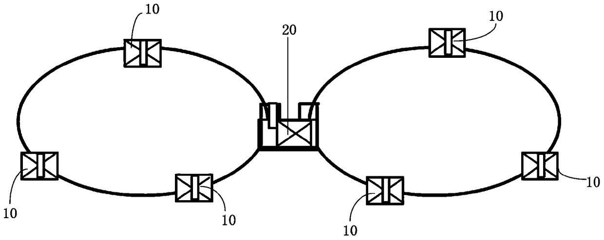
[0025] see figure 1 , the present invention provides an access control monitoring system for monitoring the opening and closing states of the doors of boxes 10 of a plurality of boxes 10 . In one embodiment of the present invention, the box 10 is an optical cross box 10 . A plurality of boxes 10 form a link, figure 1 In the illustrated embodiment, six optical cross boxes 10 are included, and every three optical cross boxes 10 are connected in series to form a link. The access control monitoring system includes a plurality of optical fiber sensors ( figure 1 Not shown in the figure) and optical link detection system 20, such as figure 1 As shown, the optical link detection system 20 is arranged between two links, and the optical link detection system 20 is connected to all ...


PUM


Abstract

Disclosed is a door control monitoring system, comprising a plurality of optical fibre sensors and an optical link detection system. The optical fibre sensors are respectively arranged at a position of the body of a case close to an edge of the door of the case. An optical fibre sensor comprises an optical fibre, a reflection module and a transmission structure. The reflection module is connected in series in the optical link detection system via the optical fibre. The transmission structure is elastically connected to the reflection module. The door of the case is closed such that the transmission structure is shifted by a force and pushes up the reflection module, so as to change the reflectivity of the reflection module. The door of the case is opened such that the transmission structure is returned back, and the reflectivity of the reflection module is restored. The optical link detection system senses the reflectivity of the reflection module, so as to monitor the opening and closing of the door of the case. The door control monitoring system of the present invention can effectively monitor various states of the door of a case, and cannot influence the service quality of a link.

Description

technical field [0001] The invention relates to the technical field of optical communication, in particular to an access control monitoring system for an outdoor optical cable transfer box. Background technique [0002] The failure of the optical fiber box door to close normally has always been a potential hidden danger to the quality of the optical fiber. There are a lot of damage phenomena, construction personnel do not follow the norms, violent construction and unlocking the door are serious. The current electronic access control is difficult to use in passive scenarios where power supply is difficult, and the overall transformation cost is very high, making it difficult to apply to ODN scenarios. In the scheme of passive sensor using optical fiber, attenuating optical fiber sensor is used. The sensor uses different bending radii to the sensing optical fiber when the box door is opened and closed, resulting in different insertion loss values. On the one hand, it is diffic...

Claims


Application Information

Patent Timeline
Patent Type & Authority Patents(China)
IPC IPC(8): H04B10/071H04B10/25G07C9/00
CPCG07C9/00H04B10/071H04B10/25
Inventor 康竞然肖志勇祁彪李三星
Owner HUAWEI TECH CO LTD
Why Eureka
Try Eureka