Physical exchange system based on E1/T1 circuit

A switching system and physical technology, applied in the field of network switching, can solve the problems of large signal switching delay, poor ease of use of switching system equipment, insufficient scalability and ease of use, etc., and the requirements to achieve frequency jitter tolerance are relaxed. , the effect of shortening the data exchange delay and simplifying the design complexity

A switching system and physical technology, applied in the field of network switching, can solve the problems of large signal switching delay, poor ease of use of switching system equipment, insufficient scalability and ease of use, etc., and the requirements to achieve frequency jitter tolerance are relaxed. , the effect of shortening the data exchange delay and simplifying the design complexity

CN101719860BActive Publication Date: 2012-05-30SUZHOU CENTEC COMM CO LTD

Image

  • Physical exchange system based on E1/T1 circuit
  • Physical exchange system based on E1/T1 circuit
  • Physical exchange system based on E1/T1 circuit

Examples


Embodiment Construction

[0027] The technical solutions of the present invention will be further elaborated below in conjunction with the accompanying drawings and embodiments.

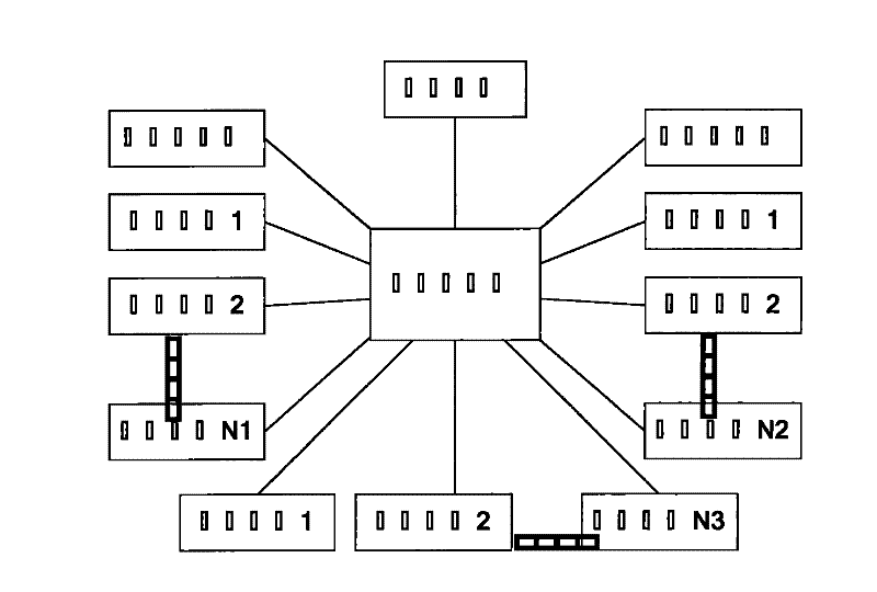
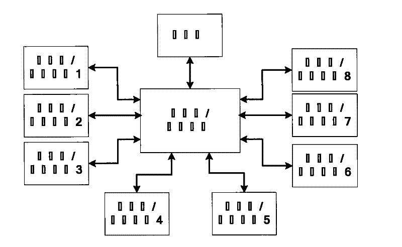
[0028] Such as Figure 2-5 As shown, the physical switching system based on the F1 / T1 circuit includes a main switching system and 8 slave switching systems, and the main switching equipment includes a processor unit (CPU), a main switching / control logic unit (FPGA), a A memory module, a power supply module, a clock module, a control serial port, a control network port and several master-slave module connectors, the memory module, the control serial port and a control network port are respectively connected to the CPU. According to the needs of practical applications, one or more of the above eight slave switching systems can be combined arbitrarily and connected to the corresponding master-slave module connectors of the main switching system through connecting lines. The port is connected to a workstation, which can configu...


PUM


Abstract

The invention relates to a physical exchange system based on an E1 / T1 circuit, which comprises a main exchange system and a plurality of independent slave exchange systems, wherein each slave exchange system is freely connected with the main exchange system which is connected with a workstation terminal, each salve exchange system is provided with at most 64 paths of E1 / T1 signal interfaces, receives signals from the E1 / T1 signal interfaces and transmits the signals to the main exchange system; meanwhile, the slave exchange systems receive output signals of the main exchange system, divide the signals into at most 64 paths of E1 / T1 signals according to the information of channel numbers in the signals and send the E1 / T1 signal out. The invention can achieve the effects of simplifying the exchange control logic and design complexity configured by a user, shortening the data exchange delay, configuring a replacement 0-delay switching, not influencing the normal service and not losing data; the quantity adjustability of system interfaces is greatly increased, the usability is greatly improved, and the requirement for frequency jitter toleration of input data is wider.

Description

technical field [0001] The invention relates to a physical layer switching system in the technical field of network switching, in particular to a physical layer switching system based on E1 / T1 communication lines. Background technique [0002] Existing switching technologies generally refer to the switching above the second layer in the OSI model (Open System Interconnection Reference Model), while the switching of the first layer, that is, the physical layer, is rarely involved. However, in some environments, we urgently need physical switches to improve the automation of work or realize real-time monitoring of multiple devices. For example, experimental devices in some laboratories may need to be frequently connected and controlled on different terminals. , the connection can be completed automatically by using a physical switch, instead of using the low-efficiency manual plugging and unplugging method for operation. Such as figure 1 The figure shown is a typical applica...

Claims


Application Information

Patent Timeline
30 May 2012
Publication
CN101719860B
IPC
H04L12/50; H04L29/08
Inventors
贾复山; 许俊