Message transceiving method and system for car CAN bus gateway
A CAN bus, message transmission technology, applied in the direction of bus network, transmission system, digital transmission system, etc., can solve problems affecting economic and social benefits, increase system load, bus competition, etc., to improve economic and social benefits. Effectiveness, guaranteed consistency, high flexibility
- Summary
- Abstract
- Description
- Claims
- Application Information
AI Technical Summary
Problems solved by technology
Method used
Image

Examples
Embodiment Construction
[0049] The present invention will be further described below in conjunction with the accompanying drawings and embodiments.
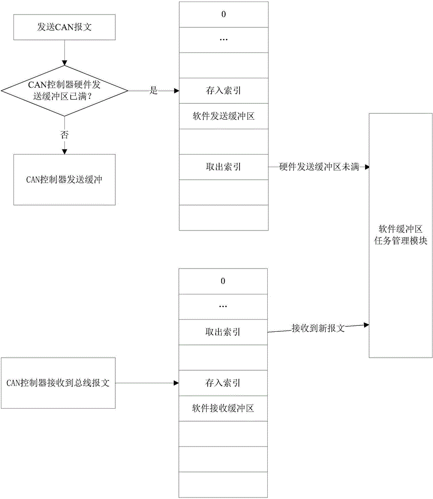
[0050] Such as figure 1 as shown,
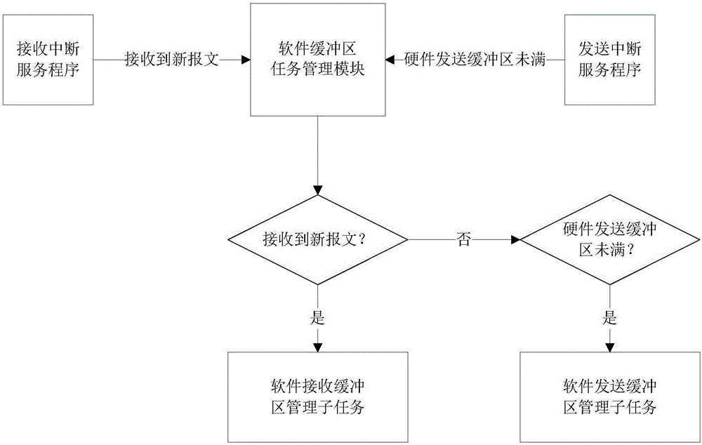
[0051] 1. Define the software receiving buffer and the software sending buffer respectively for the receiving and sending of CAN messages, establish a buffer management module, and send "new message received" or The "hardware sending buffer is not full" signal, in the buffer management module, processes the messages in the software receiving buffer and sends the messages in the software sending buffer.
[0052] 2. The software receiving buffer and software sending buffer are structure arrays, and the structure members include message ID, message length and message data. The lengths of the receiving array and the sending array are set according to the load rate of the CAN network to ensure that there will be no buffer overflow under the normal communication of the CAN network.
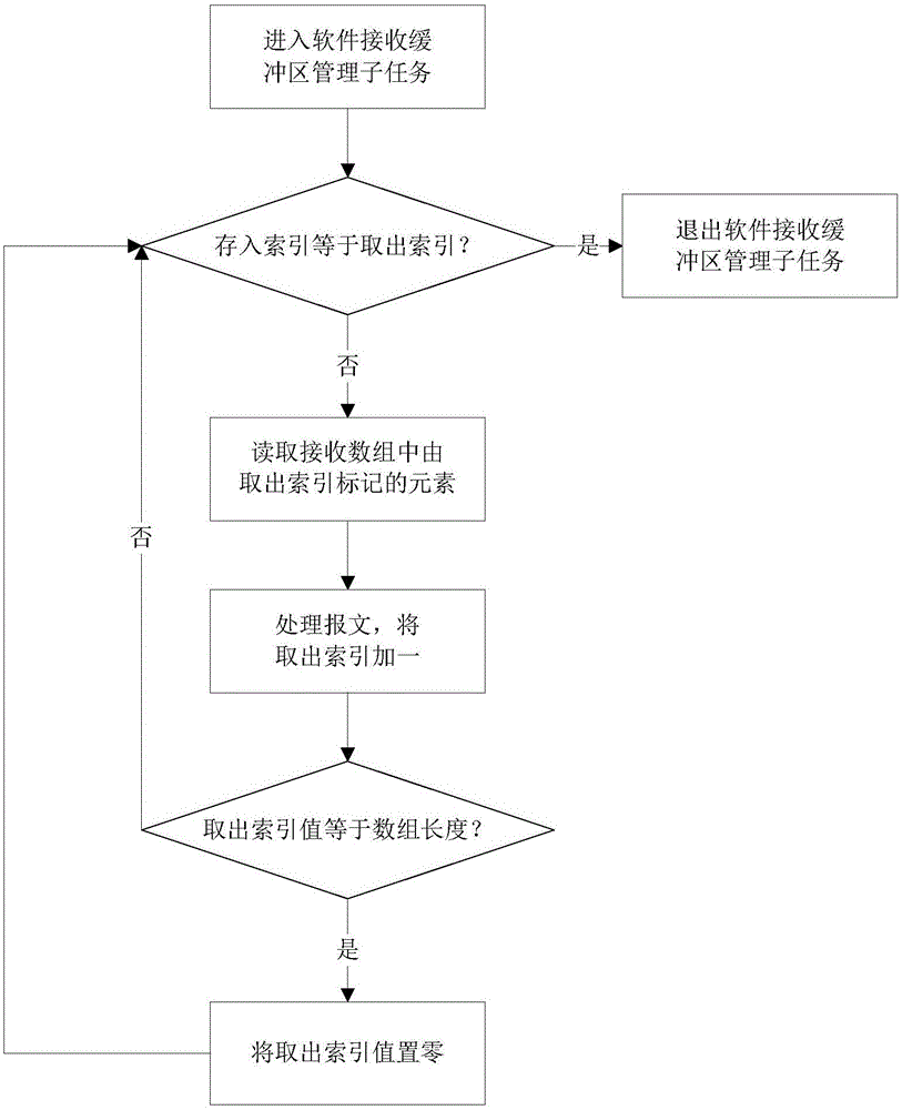
[0053] 3. Array elements are addresse...
PUM
 Abstract
Description
Claims
Application Information
 - R&D
- Intellectual Property
- Life Sciences
- Materials
- Tech Scout
- Unparalleled Data Quality
- Higher Quality Content
- 60% Fewer Hallucinations
Browse by: Latest US Patents, China's latest patents, Technical Efficacy Thesaurus, Application Domain, Technology Topic, Popular Technical Reports.
© 2025 PatSnap. All rights reserved.Legal|Privacy policy|Modern Slavery Act Transparency Statement|Sitemap|About US| Contact US: help@patsnap.com